on
ESP-01 Programmer
To accompany my ESP-01 light controllers I decided to design and build an ESP-01 programmer board. The intent is to have a easy way to flash new firmware onto my light controllers (without having to keep the flashing circuit breadboarded) and experiment with assembling a surface mount board.
I start with the following criteria:
| Item | Scope | Description |
|---|---|---|
| 1 | Must | Be able to reset and ESP-01 and enter flashing mode |
| 2 | Must | Be built with surface mount components |
| 3 | Must | Have built-in FTDI |
| 4 | Should | Be mountable on a standard sized breadboard |
| 5 | Could | Reset ESP-01 automatically using serial comm signal |
| 6 | Could | Have data transfer LEDs |
The one thing I did not do was item 5.
This project was an excerise in reading datasheets and selecting the right components.
USB to FTDI
While I technically could have used my existing FTDI breakout, I decided I wanted the programmer to have onboard FTDI. Which really does make it a self contained ESP-01 programmer.
The FTDI chip I selected was the FT23DXS as it is simply a USB+/- to RX/TX converter. Also this chip has a SSOP package with the pin exposed (Meaning I can hand solder it onto the PCB).
The following schematic shows the USB mini B connection to the FT23DXS. This circuit is taken from the FT23DXS’s datasheet.
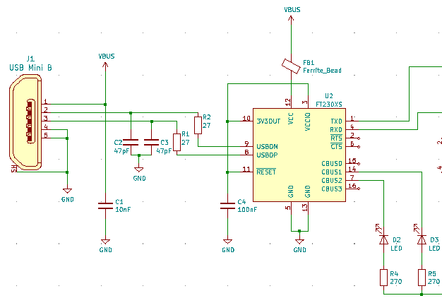
Several capacitors are used for noise filtering on the USB input.
I’ve also included RX and TX LED indications on the CBUS output pins.
3.3V Supply
The FT23DXS has a 3.3V output however it can only supply 50mA. The ESP8266 needs approximately 80mA to function so a dedicated 3.3V linear regulator was added to the board.
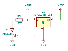
Also included an LED on the VBUS input to indicate power on.
ESP-01
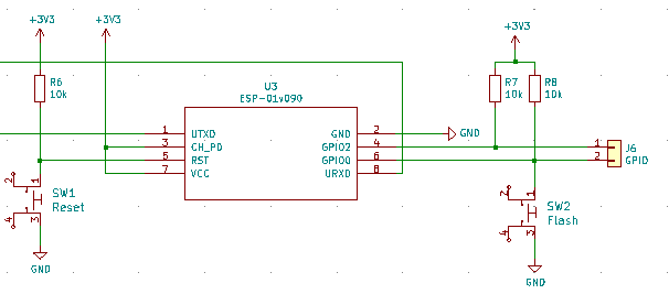
This is the flashing circuit for the ESP-01. GPIO0 and GPIO2 and pulled up for normal “boot from flash” mode. Pushbuttons were added to RST and GPIO0 to allow the board to be reset and enter programming mode. The two GPIO pins were brought out to a header.
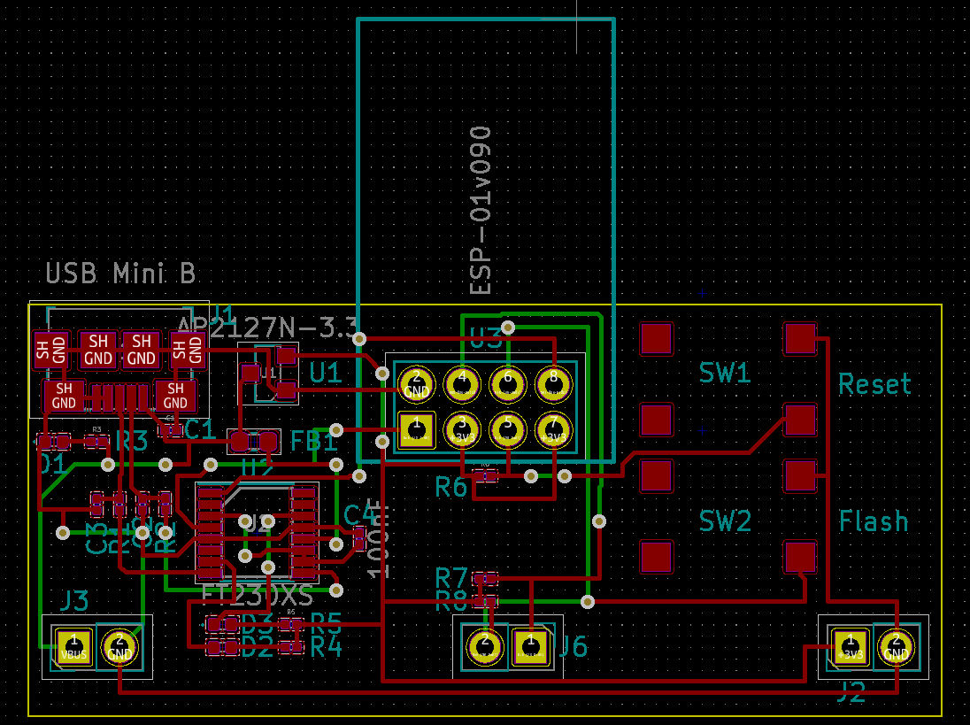
PCB Layout