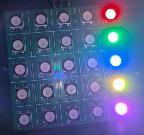
on
STM32H5 WS2812 Example
Example application of using the STM32H5 to control WS2812 LEDs using GPDMA and PWM.
What is WS2812?
A WS2812 is an addressable RGB LED (sometimes referred to as a ‘smart’ leds). Interfacing with it allows controlling it’s color and brightness. WS2812 LEDs are also daisy chainable meaning you can control an arbitrary amount of them from the same data pin.
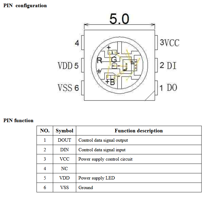
WS2812 LED Data input
To interface with the WS2812 LED you send a stream of pulses to its data input. The LED consumes 3 bytes worth of data (4 bytes if you have a RGBW LED) and forwards the rest of the pulses to it’s DOUT pin.
A single bit on the data line is encoding using the timing diagram below:
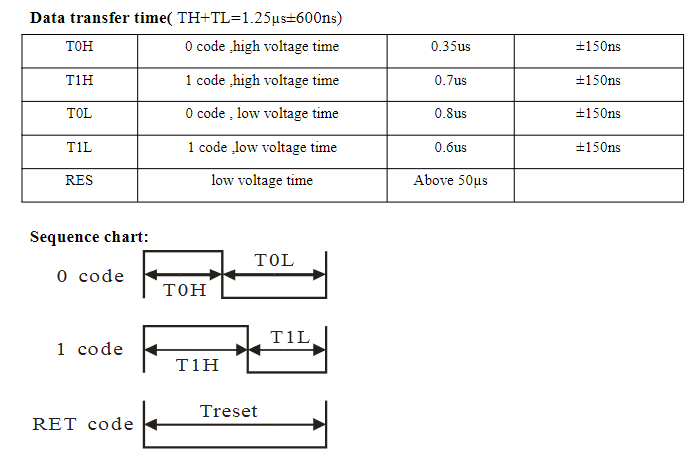
Summary:
- 1.25us waveform period -> 800,000kHz frequency waveform
- To send a 0: 0.35us high time, 0.8us low time
- To send a 1: 0.70us high time, 0.6us low time
Setting up PWM on the STM32H5
I’m using the STM32H5 Discovery Kit.
The WS2812 input will be connected PA8, D9 on the PCB, which will be mapped to the TIM1 CH1 output.
TIM1 will be configured to use the internal clock source (25MHz).
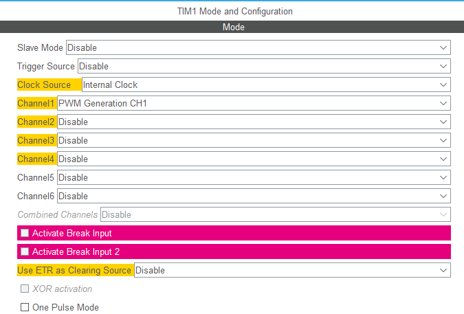
We have to do a bit of math to figure out the value of the Auto-Reload Register (ARR), to give us the desired frequency.
The PWM frequency can be determined using the following:
The prescaler will be set to 0. Which gives the following for ARR:
Substituting over values:
I decided to use 311.
I’m adding this as a user constant for reuse in the code:

And the TIM1 parameters.
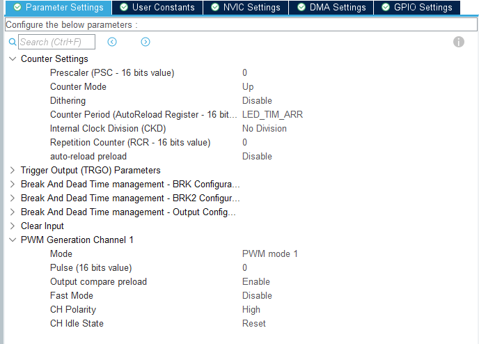
In main.c, start the PWM and set a duty cycle of 50% (ARR / 2)
int main(void)
{
  // ...
  /* USER CODE BEGIN 2 */
  HAL_TIM_PWM_Start(&htim1, TIM_CHANNEL_1);
  TIM1->CCR1 = LED_TIM_ARR / 2;

  /* USER CODE END 2 */

  /* Infinite loop */
  /* USER CODE BEGIN WHILE */
  while (1)
  {
    /* USER CODE END WHILE */

    /* USER CODE BEGIN 3 */
  }
  /* USER CODE END 3 */
}
The output looks like the following:
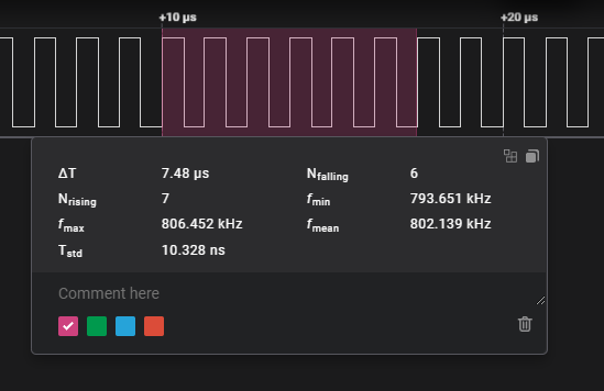
We have the approximate 800kHz waveform we need. However, we need to do a bit more to actually control the LEDs.
Setting up DMA on the STM32H5
We need more granular control over the waveform then manually setting the duty cycle can achieve. This is where using DMA comes in.
GPDMA (General Purpose Direct Memory Access), has more configuration options then you might see on an F3 or F4.

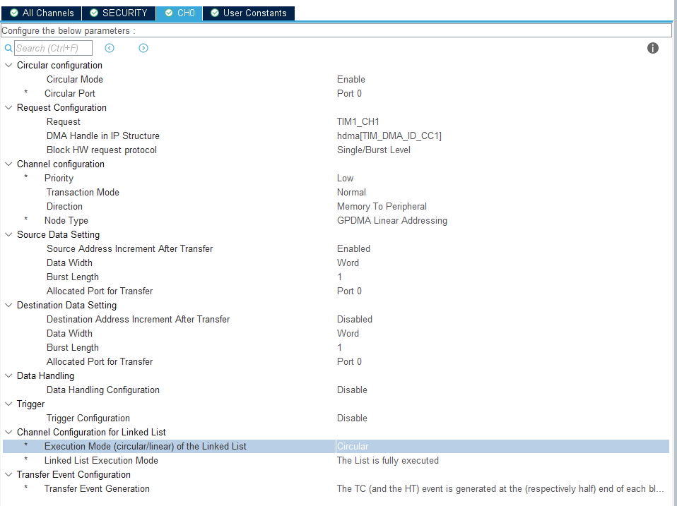
This configs the DMA controller to
- Output to TIM1 CH1
- Transfer data between memory and a peripheral (the timer)
- The source destination address will be auto incremented
- The data width and burst length for the source and destination are 32-bits and 1 respectfully
Also note circular mode must be enabled to, somewhat unintuitively, enable linked list mode.
Code for a single LED transfer
/* Private define ------------------------------------------------------------*/
/* USER CODE BEGIN PD */
#define LED_PULSE_HI ((LED_TIM_ARR / 3) * 2)
#define LED_PULSE_LO ((LED_TIM_ARR / 3) * 1)

#define NUM_LEDS 1
#define NUM_LEDS_PER_TRANSFER 1

#define BYTES_PER_LED 3
#define BITS_PER_LED (BYTES_PER_LED * 8)

#define NUM_TRANSFER_ELEMENTS (BITS_PER_LED * NUM_LEDS_PER_TRANSFER)

#define LED_BUFFER_SIZE (BYTES_PER_LED * NUM_LEDS)
#define PWM_BUFFER_SIZE (NUM_TRANSFER_ELEMENTS)

#define NUM_TRANSFER_BYTES (PWM_BUFFER_SIZE * sizeof(uint32_t))

/* USER CODE BEGIN PV */
static uint8_t led_buffer[LED_BUFFER_SIZE] = {0};
static uint32_t pwm_buffer[PWM_BUFFER_SIZE] = {0};
Manually assigning the PWM data for a single LED.
  /* USER CODE BEGIN 2 */
  // G
  pwm_buffer[0] = LED_PULSE_HI;
  pwm_buffer[1] = LED_PULSE_HI;
  pwm_buffer[2] = LED_PULSE_HI;
  pwm_buffer[3] = LED_PULSE_HI;
  pwm_buffer[4] = LED_PULSE_HI;
  pwm_buffer[5] = LED_PULSE_HI;
  pwm_buffer[6] = LED_PULSE_HI;
  pwm_buffer[7] = LED_PULSE_HI;
  // R
  pwm_buffer[8] = LED_PULSE_LO;
  pwm_buffer[9] = LED_PULSE_LO;
  pwm_buffer[10] = LED_PULSE_LO;
  pwm_buffer[11] = LED_PULSE_LO;
  pwm_buffer[12] = LED_PULSE_LO;
  pwm_buffer[13] = LED_PULSE_LO;
  pwm_buffer[14] = LED_PULSE_LO;
  pwm_buffer[15] = LED_PULSE_LO;
  // B
  pwm_buffer[16] = LED_PULSE_LO;
  pwm_buffer[17] = LED_PULSE_LO;
  pwm_buffer[18] = LED_PULSE_LO;
  pwm_buffer[19] = LED_PULSE_LO;
  pwm_buffer[20] = LED_PULSE_LO;
  pwm_buffer[21] = LED_PULSE_LO;
  pwm_buffer[22] = LED_PULSE_LO;
  pwm_buffer[23] = LED_PULSE_LO;

  HAL_TIM_PWM_Start_DMA(&htim1, TIM_CHANNEL_1, pwm_buffer, NUM_TRANSFER_BYTES);
Note: HAL_TIM_PWM_Start_DMA(TIM_HandleTypeDef *htim, uint32_t Channel, const uint32_t *pData, uint16_t Length) takes a uint32_t* but the Length is in bytes not words.
We’ll also have to stop the transfer when the transfer is complete
/* USER CODE BEGIN 4 */
void HAL_TIM_PWM_PulseFinishedCallback(TIM_HandleTypeDef *htim)
{
  HAL_TIM_PWM_Stop_DMA(&htim1, TIM_CHANNEL_1);
}
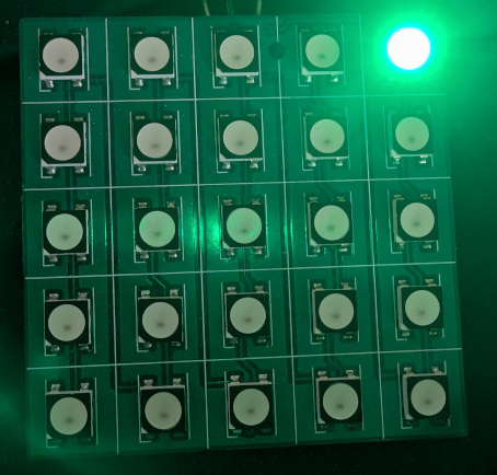
This will turn on a single LED green.

Converting LED data into PWM data
We can iterate over each bit in the LED data and dtermine if it should be a HIGH or LOW pulse in the PWM buffer.
/* USER CODE BEGIN 0 */
void setColor(const size_t idx, uint8_t r, uint8_t g, uint8_t b)
{
  led_buffer[(BYTES_PER_LED * idx) + 0] = r;
  led_buffer[(BYTES_PER_LED * idx) + 1] = g;
  led_buffer[(BYTES_PER_LED * idx) + 2] = b;
}

uint32_t getColor(const size_t idx)
{
  const uint32_t r = (uint32_t)led_buffer[(BYTES_PER_LED * idx) + 0];
  const uint32_t g = (uint32_t)led_buffer[(BYTES_PER_LED * idx) + 1];
  const uint32_t b = (uint32_t)led_buffer[(BYTES_PER_LED * idx) + 2];

  return (g << 16) | (r << 8) | b;
}

void updatePwmData()
{
  int idx = 0;
  for (int i = 0; i < NUM_LEDS; ++i)
  {
    const uint32_t color = getColor(i);

    for (int bit = 23; bit >= 0; --bit)
    {
      if (color & (1 << bit))
      {
        pwm_buffer[idx] = LED_PULSE_HI;
      }
      else
      {
        pwm_buffer[idx] = LED_PULSE_LO;
      }

      idx++;
    }
  }
}

int main(void)
{
  // ...

  /* USER CODE BEGIN 2 */
  setColor(0, 0xFF, 0x00, 0x00);
  updatePwmData();

  HAL_TIM_PWM_Start_DMA(&htim1, TIM_CHANNEL_1, pwm_buffer, NUM_TRANSFER_BYTES);

  // ...
}
Code for transferring multiple LEDs
Holding a 32-bit value per bit of RGB data will use an excessive amount of RAM. So we have to be a little smarter on managing the LED buffer.
We’re going to hold enough data for 2 LEDs and update the buffer on the fly using the half complete and transfer complete interrupts.
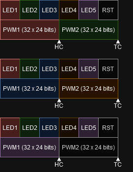
The GPDMA controller will provide callback for when the transfer is half complete (HC) and fully complete (TC).
We will keep track of the current LED index. When the HC interrupt fires we will write the current LED index into the first 24 PWM data elements. Then the TC interrupt fires we will write the current LED index into the second half of PWM data.
The DMA controller will be constant writing so we will also need to handle the 50us reset period the WS2812 LEDs need.
/* Private typedef -----------------------------------------------------------*/
/* USER CODE BEGIN PTD */
typedef enum Event {
  DMA_HalfComplete,
  DMA_TransferComplete
} DmaEvent;

/* Private define ------------------------------------------------------------*/
/* USER CODE BEGIN PD */

// ...

#define NUM_LEDS 5
#define NUM_LEDS_PER_TRANSFER 2

#define NUM_TRANSFERS_FOR_RESET 40 // 50us / 1.25us

// ...

/* Private user code ---------------------------------------------------------*/
/* USER CODE BEGIN 0 */

// ...

void updatePwmDataForLedAtOffset(const size_t led, const size_t offset)
{
  const uint32_t color = getColor(led);

  int idx = 0;
  for (int bit = 23; bit >= 0; --bit)
  {
    if (color & (1 << bit))
    {
      pwm_buffer[offset + idx] = LED_PULSE_HI;
    }
    else
    {
      pwm_buffer[offset + idx] = LED_PULSE_LO;
    }

    idx++;
  }
}

void updatePwmDataForReset(const size_t offset)
{
  for (int i = 0; i < BITS_PER_LED; ++i)
  {
    pwm_buffer[offset + i] = 0;
  }
}

void handleTransferEvent(const DmaEvent dma_event)
{
  const size_t offset = (dma_event == DMA_HalfComplete) ? 0 : BITS_PER_LED;

  if (current_led < NUM_LEDS)
  {
    updatePwmDataForLedAtOffset(current_led++, offset);
  }
  else
  {
    // Reset period
    updatePwmDataForReset(offset);
    current_led++;
  }

  if (current_led >= (NUM_LEDS + NUM_PULSES_FOR_RESET))
  {
    current_led = 0;
  }
}

void HAL_TIM_PWM_PulseFinishedCallback(TIM_HandleTypeDef *htim)
{
  handleTransferEvent(DMA_TransferComplete);
}

void HAL_TIM_PWM_PulseFinishedHalfCpltCallback(TIM_HandleTypeDef *htim)
{
  handleTransferEvent(DMA_HalfComplete);
}

