References
Screen Timing
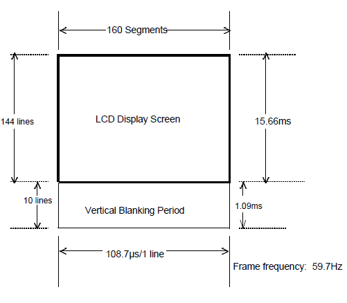
- 60 Hz frame rate - 16.6 ms period
- V-Blank lasts 1.09 ms
LCDC Control Register
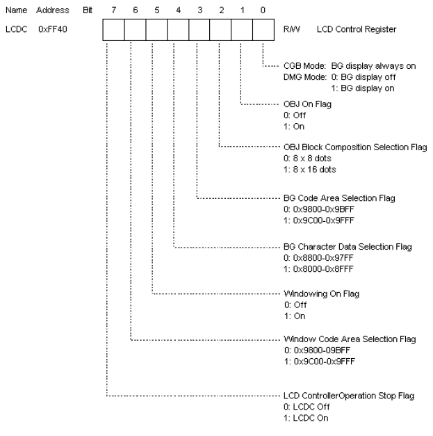
LCDC control register.
Configures how object data is read and where it is read from.
STAT Register
LCD controller status and interrupt configuration.
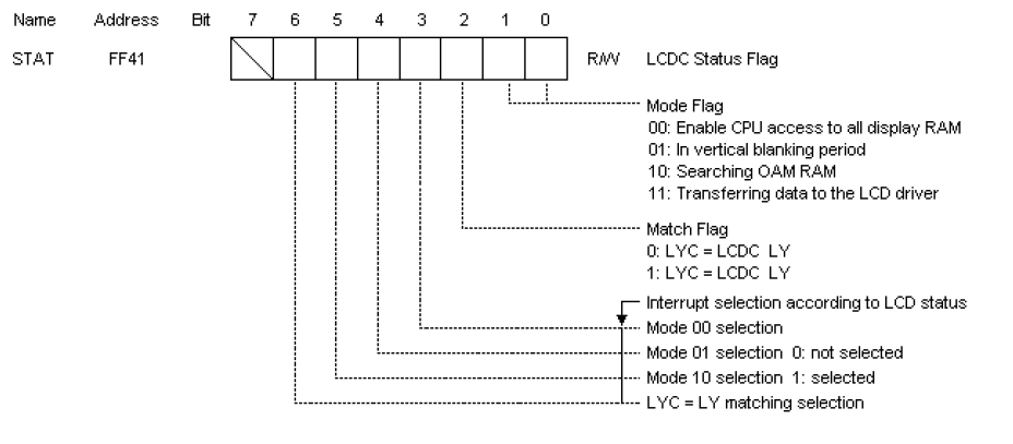
Indicates current status of LCD controller module in the CPU.
- Mode Flag (Bits 1:0) is the current LCDC mode.
- Mode selection (Bits 6:3) Configure what interrupts the LCD controller will produce.
LCD controller interrupts
| Bit | Name |
|---|---|
| 6 | LYC = LY Interrupt |
| 5 | Mode 2 OAM Interrupt |
| 4 | Mode 1 V-Blank Interrupt |
| 3 | Mode 0 H-Blank Interrupt |
Mode 0
- Horizontal blanking period
- CPU has access to display RAM
$8000 - $9FFF
Mode 1
- Vertical blanking period
- For approximately 1 ms CPU has access to display RAM
$8000 - $9FFF
Mode 2:
- Searching OAM and display RAM period
- OAM
$FE00 - $FE90is being access by the LCD controller and is not accessible to the CPU
Mode 3:
- Transferring data to LCD driver period
- LCD controller is using both OAM
$FE00 - $FE90and display RAM$8000 - $9FFFand can not be accessed by the CPU
LCDC Mode Timing Diagram
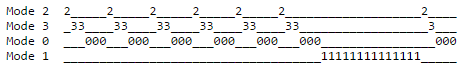
Mode 0 is present between 201-207 clks, 2 about 77-83 clks, and 3 about 169-175 clks. A complete cycle through these states takes 456 clks. VBlank lasts 4560 clks. A complete screen refresh occurs every 70224 clks.)
LCDC Y-Coordinate Registers
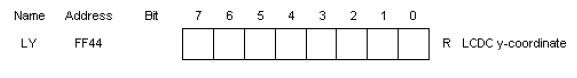
LY indicate which line of data is being transferred to the LCD display driver.
- Takes values 0 - 153
- 144 - 153 is the Vertical blanking period
When the LCDC goes from ON to OFF, LY is reset to 0.
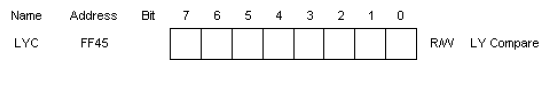
LYC is used to compare a value to the LY register. If they match the match flag is set in the STAT register.
This can be used to invoke an interrupt when LY reaches a particular scan line.
Blanking Periods

LCD driver scans across each line segment to display memory on the screen. The H-Blank period is the time it takes to re-position to the start of the next scan line. The V-Blank period is the time it takes the LCD driver to re-position to the first line.