on
Quadruped Prototype
The last month or two I’ve been working on a quadruped robot prototype. I’ve not got it walking yet, but here is the overall progress so far.
Scope
- An 8 DOF quadruped (4 legs, 2 servos each).
- Some form of RC control
Design
Vitamins
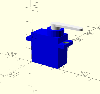
Continuing to use OpenSCAD for 3D modelling. The first step is to create vitamins for the components that will be used in the project. For now that would be the micro 9g servos.
I’ve created a separate project for this and included it as a OpenSCAD library. I won’t be copying all the OpenSCAD code here, but the general pattern is to create an array containing the data that defines the model you want to render, and then write a function that does the rendering.
For example in servos.scad:
SG90 = [
    // Base dimensions
    [22.8, 12.3, 22.5],
    // Screw bar (???) dimensions
    [32.2, 12.3, 2.5],
    // Column height above base
    30.0 - 3.2,
    // Axiel radius
    4.9 / 2,
    // Axiel height
    30.0,
    // Screw hole radius
    2.0,
    // Screw hole from each other
    // 27.5
];
I define a parameter set that describes the SG90 servo and use the function servo to render it:
include <vitamins/servos.scad>
include <vitamins/servo_joints.scad>

servo = SG90;

axiel_offset = servo_axiel_offset(servo);

translate([axiel_offset[0], axiel_offset[1], servo_column_height(servo)]) {
    servo_joint1(SG90_JOINT1);
}

servo(servo);
I’ve also added models for the joint/connectors for the servo.
Leg/Foot Design
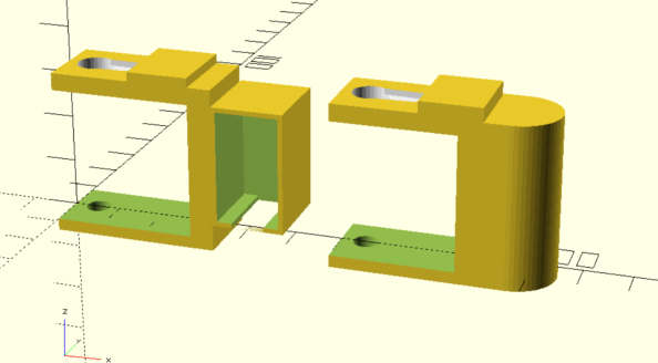
A single leg of the quadruped is one servo mounted 90 degrees from the other. The “leg” is the piece that connects to the main body and the foot is the piece that makes contact with the ground.
Here is what they look like individually (leg on the left, foot on the right):
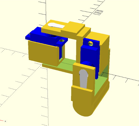
Assembly with servos:
Main Body
Of course the servo controlling the “leg” must be connected to the main body of the quadruped. The main body is literally just a rectangle with the servo “holder” on all four corners. Future designs will include a place for the microcontroller and batteries.
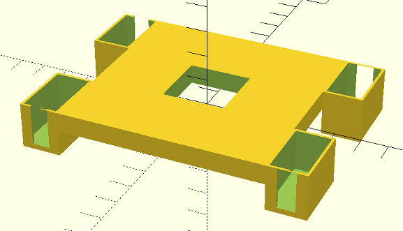
Assembly with all four legs:
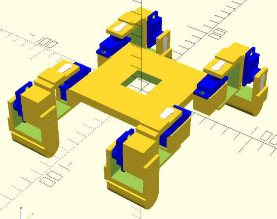
I’ll explain the hole in the center in the next section.
Prototyping / Iteration
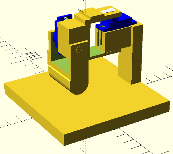
Having the full assembly done is nice, but not a good use of time/pla to print everything only to find it doesn’t work. So instead I’ve designed a mount for a single leg to test the inverse kinematics code.
Single leg mount:
And assuming a single leg works it would still be useful to have the entire robot elevated to test the walking code and avoid a tangle of wires.
I designed a model to prop the main body up, with room for a bread board to sit inside. The hole in the the center of the main body is to route the servo cables through, to prevent the leg/feet from yanking on the wires.
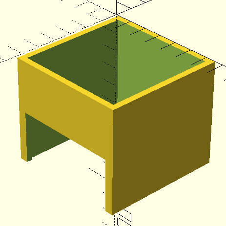
This model was just thrown together and the intent is just to tape the main body to it so it doesn’t fall off.
Inverse Kinematics
I’m by no means a math expert so I’ll be referring to the article “Development of an 8DOF quadruped robot and implementation of Inverse Kinematics using Denavit-Hartenberg convention”1.
The main idea is I want to place the foot (end effector) at a particular (x,y,z) in space, and calculate the servo angles required to achieve that.
Given that this is a 8 DOF quadruped and only has two angles to solve for, the solution is relatively easy to do analytically.
Take the follow diagram1:
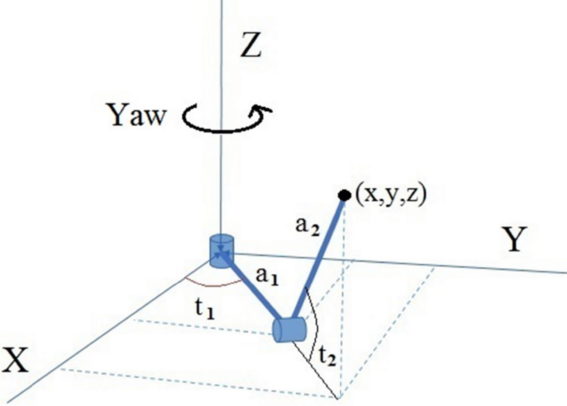
\begin{equation} t_1 = {\arctan {y \over x}}. \end{equation}
\begin{equation} t_2 = {\arctan {z \over \sqrt{x^2+y^2}-a_1}}. \end{equation}
Now for any given (x, y, z) the angles t1 and t2 can be found.
Visualization
To sanity check my inverse kinematic calculations I created a 3D visualization using bevy game engine. Why bevy? I want to write the firmware in Rust, so I created a common “locomotion” crate shared between the firmware binary and the visualization app. Bevy was the easiest 3D engine to use in Rust that I could find.
The code to do the above equations:
fn calc_joint_angles(p: Point, link_offset: f32) -> (f32, f32) {
    (
        p.y.atan2(p.x),
        p.z.atan2((p.x.powf(2.0) + p.y.powf(2.0)).sqrt() - link_offset)
    )
}
Where link_offset is the value of a1 or a2, in this case assumed to be the same.
The visualization:
- Two blocks representing the links in the leg
- The red sphere is the end effector (foot)
I’ve setup a path spline, shown by the blue points. A point on the spline is determined using a value between 0 and 1. That point is fed into the inverse kinematic equations to calculated the joint angles. The joint angles are then assigned to the rotation of the 3D models.
At this point its a matter of writing the firmware to control the actual servos.
Firmware
I’m using my STM32 Discovery kit, so the setup is similar to the Embedded Rust book.
#![no_std]
#![no_main]

use cortex_m_semihosting::hprintln;
use panic_semihosting as _;

use f3::{
    hal::{delay::Delay, i2c::I2c, prelude::*, stm32f30x},
    led::Led,
};
use pwm_pca9685::{Address, Channel, Pca9685};

use locomotion::{Engine, math::scale};

#[cortex_m_rt::entry]
fn main() -> ! {
    let cp = cortex_m::Peripherals::take().unwrap();
    let dp = stm32f30x::Peripherals::take().unwrap();

    let mut flash = dp.FLASH.constrain();
    let mut rcc = dp.RCC.constrain();
    let mut gpioe = dp.GPIOE.split(&mut rcc.ahb);
    let clocks = rcc.cfgr.freeze(&mut flash.acr);

    let mut delay = Delay::new(cp.SYST, clocks);

    // Setup I2C and PWM controller
    let mut gpiob = dp.GPIOB.split(&mut rcc.ahb);
    let scl = gpiob.pb6.into_af4(&mut gpiob.moder, &mut gpiob.afrl);
    let sda = gpiob.pb7.into_af4(&mut gpiob.moder, &mut gpiob.afrl);

    let i2c = I2c::i2c1(dp.I2C1, (scl, sda), 100.khz(), clocks, &mut rcc.apb1);

    let mut pwm = Pca9685::new(i2c, Address::default()).unwrap();
    // This results in about 50 Hz, which is the frequency at which servos operate.
    pwm.set_prescale(100).unwrap();
    pwm.enable().unwrap();
    // Turn all channels on at time "0".
    pwm.set_channel_on(Channel::All, 0).unwrap();

    // Locomotion engine
    let mut engine = Engine::new(3.0);

    // You need to tweak these min/max values for your servos as these may vary.
    let servo_min = 165; // minimum pulse length (out of 4096)
    let servo_max = 610; // maximum pulse length (out of 4096)

    loop {
        engine.update();

        let channels = [
            (Channel::C0, Channel::C1), (Channel::C2, Channel::C3),
            (Channel::C4, Channel::C5), (Channel::C6, Channel::C7),
        ];

        for (i, (channel_a, channel_b)) in channels.iter().enumerate() {
            let idx0 = (i * 2) as u32;
            let idx1 = ((i * 2) + 1) as u32;

            let angle0 = engine.joint_angle(idx0).to_degrees();
            let pulse0 = scale(angle0, -90.0, 90.0, servo_min as f32, servo_max as f32) as u16;
            let angle1 = engine.joint_angle(idx1).to_degrees();
            let pulse1 = scale(angle1, -90.0, 90.0, servo_min as f32, servo_max as f32) as u16;

            pwm.set_channel_off(*channel_a, pulse0).unwrap();
            pwm.set_channel_off(*channel_b, pulse1).unwrap();

            delay.delay_ms(200_u16);

            // Turn channel off to conserve current
            pwm.set_channel_full_off(*channel_a).unwrap();
            pwm.set_channel_full_off(*channel_b).unwrap();
        }
    }
}
The Engine is what set the end effector point for each leg. This code is setting all channels but only the first two are connected.
Resulting in:
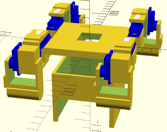
Full Assembly
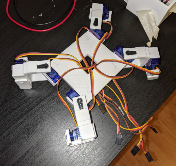
I’m still working on the locomotion code. But here is the robot propped up so I can iterate on the code.
References
2 posts reference this page