It’s been many years since I’ve done a project like this. Not since my HCS12 Controller back in college. While Arduino is great, something about buying a board off-the-shelf just isn’t the same as doing it DIY. Though this way can be much more time consuming, prone to errors and expensive, it is much more satisfying.
This year I’ve done a few projects:
I’ve also been dabbling with the thought of getting into DIY drones.
The one thing they have in common is driving motors using PWM. Most open hardware/software drone projects typically advertise a “Rover” mode. There’s no reason to consider the core of a drone or a rover application to be particularly different.
Icarus was originally my attempt at a flight controller, that I broadened the scope of a bit and generalized to the various projects I wanted to work on.
The goal would be to create a handful of small stackable PCBs:
- Kratos PDB for power distribution
- Icarus controller supplying logic and PWM outputs
- And
Nshield(s) that stack onto icarus (for example an H-bridge shield for a diff-drive robot)
Scope
The scope of this project is to design and build an embedded system that can be used as a controller for multiple robotics projects. Specifically it should be able to drive: diff-drive robots, quadrupeds (8 DOF) and mirco-quads
| Reference # | Priority | Item |
|---|---|---|
| R1 | Must | Support at least 4 motors |
| R2 | Must | Have motion sensing capabilities |
| R3 | Must | Be remote controllable |
| R4 | Should | Have USB 2.0 support |
| R5 | Could | Control up to 8 motors (for more elaborate projects) |
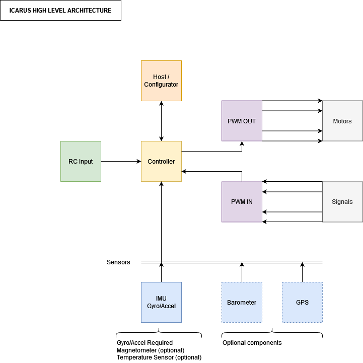
Architecture
| Reference # | Description |
|---|---|
| R1 | PWM output to drive motors. There is also PWM input for encoder feedback |
| R2 | An IMU can be used for motion sensing. At minimum a gyro and accelerometer would be required |
| R3 | RC input would be require as input to the controller |
Power Supply
Required Power Inputs
Motorized applications typically require two types of power: Logic power for digital components and analog power for the motors.
Power Supply Inputs
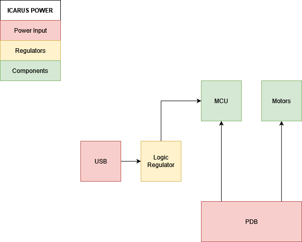
The board will have two inputs for power:
- Voltage input pins from a PDB (supplying logic and motor power)
- 5V input from a USB connector (supplying just logic power)
The PDB will be the main supply for a project. The USB power will be for debugging / flashing the MCU.
| Power Type | Voltage Level (V) |
|---|---|
| Logic Power | 3.3 |
| Analog / Motor Power | Unregulated main supply voltage |
| USB (VBUS) | 5 |
An onboard regulator will be required to convert VBUS to the appropriate logic level.
Onboard Linear Regulator
As mentioned above, the board will have to regulate the VBUS input down to 3.3V for logic power.
Selected regulator is the AMS1117-3.3:
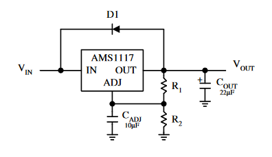
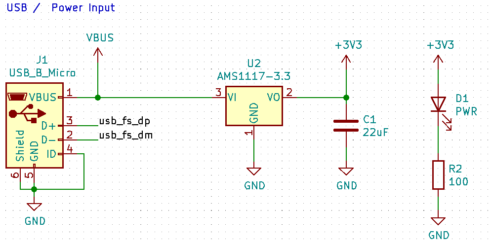
I’m using the non-adjustable version so the diode and feedback resistors can be omitted. The output capacitor is the recommended 22uF tantalum cap.
Power supply schematic
Power Distribution Board
The power distribution board will actually be a separate project: Kratos PDB
Sensors
Determine what sensors should be on the controller given the high level requirements.
Sensor Requirements
As one of the purposes of this controller is for drones, understanding orientation in the air will be critical.
There are degrees to orientation sensing and what is required to achieve them, see below:
| Orientation Frame | Requirement Sensors |
|---|---|
| Inertial | Accelerometer, Gyroscope |
| World | Accelerometer, Gyroscope, Magnetometer |
Inertial frame orientation would be the drone orientation with respect to where it started.
World space orientation would be with respect to a fixed position on Earth like magnetic north (which is why it requires a magnetometer)
Other sensors:
- Barometer
- GPS
Sensor Selection
For the first revision of this board I’ve chosen a single sensor: The MPU6050.
This sensor includes both an accelerometer and a gyroscope which should be sufficient for basic attitude sensing. In future revisions I’ll considering add a magnetometer as it can be added to the fusion algorithm.
MCU
MCU Requirements
The following is the requirements of the MCU given the high level architecture.
Motor Drive
This project is intended to drive at least 4 DC motors for a quad-copter and up to 8 motors for a 8 DOF quadruped. In both cases, multiple 50Hz PWM outputs are required.
The board should also be the core of any diff-drive robotics projects, however in order to accomplish that an H-bridge would be required. For that application, an H-bridge IC could be part of a “shield”. Inclusion of the H-bridge on this board will depend on the space requirements.
Ideally the MCU support some type of motor feedback. It could be encoder pulse counting or ADC input from servo position feedback.
Sensors
Typically various sensors would communicate over I2C or SPI.
RC Input
In the context of drones there are a number of different receiver types. The fall mostly fall into two categories:
- Serial input (i.e. UART)
- PWM input
The MCU should support both of these input types.
Host Configuration
There will have to be some way to flash / configure the controller. It makes sense to do this over a USB-Serial or USB connection.
MCU Selection
The MCU requirements for this project are pretty basic:
- 4 PWM outputs (Up to 8)
- PWM inputs
- 2x USART
- 1x I2C
- Optional USB support
A lot of common micro-controllers will cover these basic peripherals (USB is less common but optional for this project)
I had two go to options:
- STM32Fx
- nRF52840
The STM32 is very common with a lot of reference designs, forum posts, tutorial, blogs, etc. It is also commonly using flight controllers and has ready to use firmware packages (Betaflight).
The nRF52840 has built in BLE and is a smaller package. This is the microcontroller on the Arduino Nano BLE 33 IOT Sense board (the one I’m using on the nanodrone project). Using the BLE hardware will require an antenna, and I can’t seem to find a NINA module on JLCPCB.
Both are ARM processors.
I plan on getting this board assembled using JLCPCB. So the MCU selection is limited to what is available in their assembly library.
| **MCU** | **PWM** | **USART** | **I2C** | **USB** | **Package** |
| STM32F407ZGTx | 17 timers, 4 channels each | Up to 4 USART Up to 2 UART | Up to 3 | USB 2.0 | LQFP144 (20mmx20mm) |
| STM32F302C8T6 | Up to 9 timers One 32 bit timers - 4 PWM One 16 bit timers - 6 PWM Three 16 bit timers - PWM | Up to 3 | 3 | USB 2.0 | LQFP48 (7mmx7mm) |
I settled on an STM32F302 for the following reasons:
- Commonly used in flight controllers
- Commonly used in general
- Had required peripherals including USB 2.0
- Well supported with Rust
No integrated BLE means the RC input MUST be external to the PCB.
STM32 Peripheral Usage
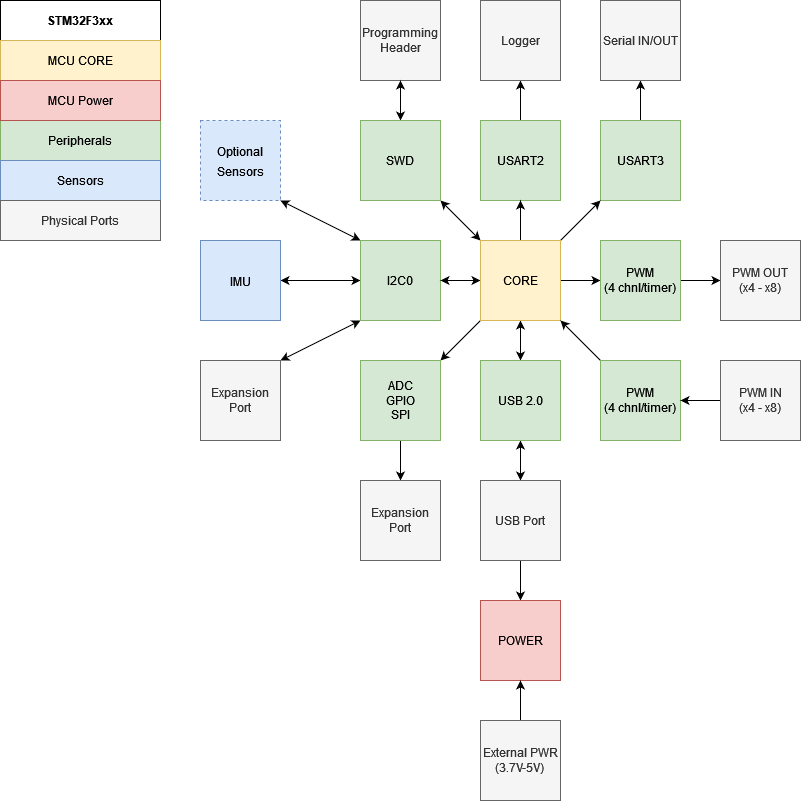
This is a rough break down of what peripherals will be used to achieve the above requirements.
- Motors will be driving from PWM outputs (x8)
- There will be PWM input channels for either encoder feedback or RC input
- Sensors will primary be connected to I2C (some may be connected over SPI)
- Host configuration will be done over USB ideally (can fallback to a UART channel if it doesn’t go well)
- ADC, GPIO and SPI will be broken out for add-ons
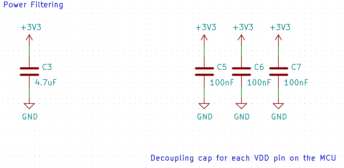
Power Supply Scheme
Of course the MCU needs to be powered appropriately and this usually involves a handful of decoupling capacitors close to the MCU VCC pins.
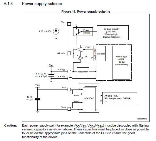
Following the recommendations from the data sheet the filtering network looks like the following:
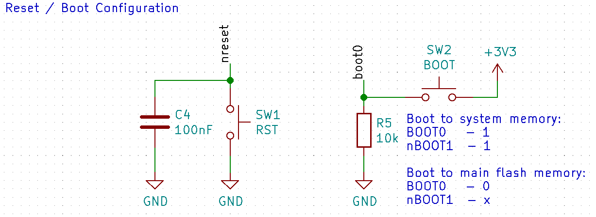
Reset Network and Boot Configuration
The device also has to boot into the correct mode and must be resettable as well.
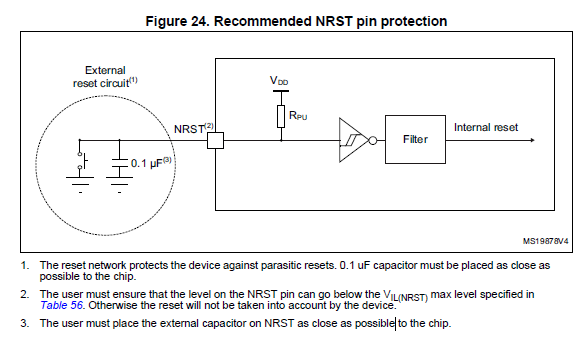
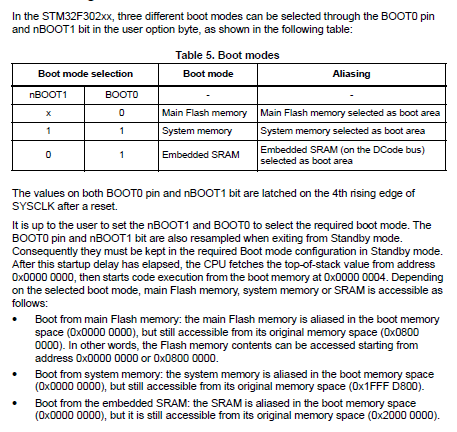
Two push buttons are used to select the boot mode and reset the MCU if needed.
Debug Support
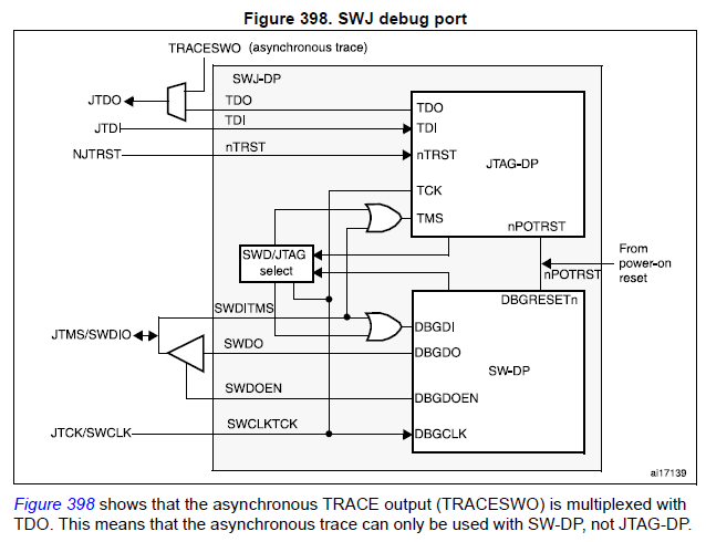
For debug support I decided to just use SWD and the standard 10 pin header
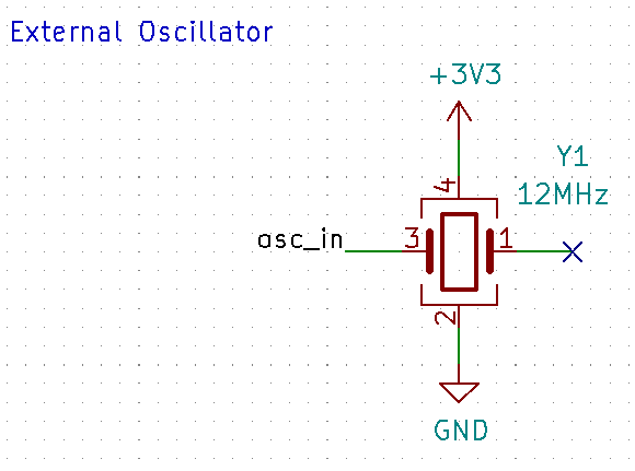
Oscillator Design
Ideally this board will use USB communication to talk to the host PC for configuration / debugging. The USB peripheral clock requires a 48MHz signal with a maximum variance or 500ppm (0.05%). The internal high speed oscillator (HSI) has a variance of 1.0%. Therefore an external oscillator is required. It is usually called out in the data sheet that an external OSC is required for USB operation.
I decided to use a 12MHz OSC package, it should provide the clock signal on its own without the need of the STM32’s OSC_OUT pin. This means the HSE must be configured to BYPASS mode.
I felt this was easier then selecting the correct crystal and capacitor and I didn’t want to make a mistake picking a crystal with the wrong drive level.
PWM Input / Output
PWM Usage:
| Application | Max PWM Output | Max PWM Input |
|---|---|---|
| Drone | 4 | 4 |
| Diff Drive | 2 | 2 |
| 8DOF Quadruped | 8 | 0 |
Timer Comparison:
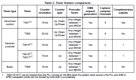
| Timer | Usage |
|---|---|
| Advanced Timer (TIM1) | 4 PWM |
| General Purpose Timer (TIM2) | 4 PWM |
Pin Mapping
| **Pin** | **Usage** | **Category** |
| PA0 | TIM2 CH1 | PWM |
| PA1 | TIM2 CH2 | PWM |
| PA2 | TIM2 CH3 | PWM |
| PA3 | TIM2 CH4 | PWM |
| PA4 | IO | LED |
| PA5 | IO | LED |
| PA6 | TIM16 CH1 | PWM |
| PA7 | TIM17 CH1 | PWM |
| PA9 | USART1 TX | Serial Comms |
| PA10 | USART1 RX | Serial Comms |
| PA11 | USB DM | USB Comms |
| PA12 | USB DP | USB Comms |
| PA13 | JTMS/SWDIO | Debugger |
| PA14 | JTCLK/SWCLK | Debugger |
| PB3 | USART2 TX | Serial Comms |
| PB4 | USART2 RX | Serial Comms |
| PB5 | IMU INT | IMU INT |
| PB6 | I2C1 SCL | I2C |
| PB7 | I2C1 SDA | I2C |
| PB13 | SPI2\_SCK | SPI, GPIO |
| PB14 | SPI2\_MISO | SPI, GPIO |
| PB15 | SPI2\_MOSI | SPI, GPIO |
Note: I’ve been designing this with a 8DOF quadruped in mind but given the MCU availability and available timers I couldn’t quite make this work.
The maximum number of PWM pins will be 6 for the Rev A Icarus board.
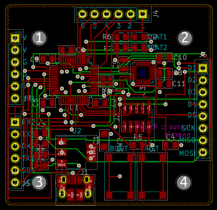
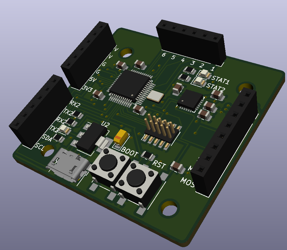
PCB Layout / Stacks
My initial thought was to create a layout that I could use to interface with the PDB and create “shields” in the future.
The PCB also needs to conform to the standard drone mounting holes.
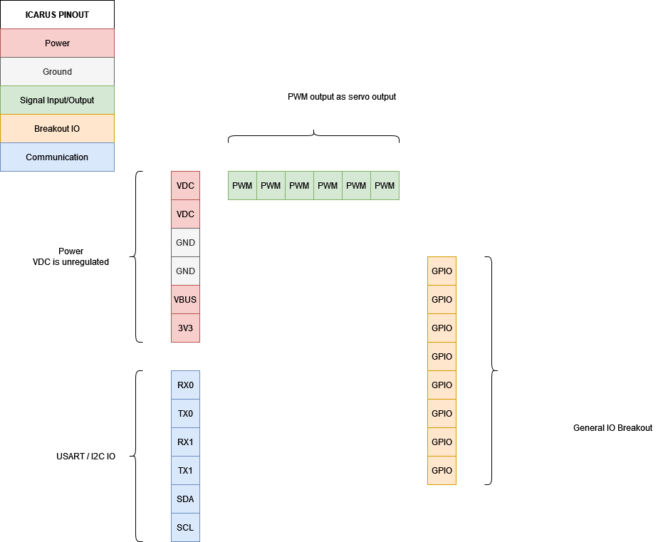
- USART2 / USART3
- PWR (3.3V, VBUS, VDC)
- 8x PWM OUT
- USB
- Extra breakouts (I2C / GPIO)
4 posts reference this page