So my next step in developing the flight controller is to strap it to a frame and exercise the motors.
Now, part of my original motivation for starting this project was taking apart a toy drone and seeing that the hardware was not too complicated.
Toy drone for reference:
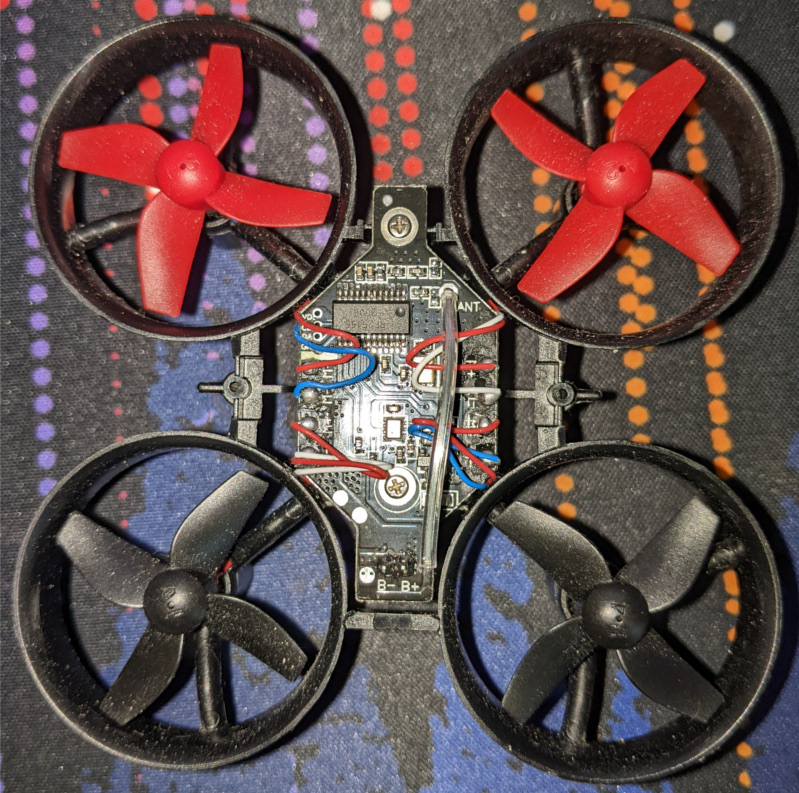
So I’m using the same motors and LiPo as the toy I bought. I went into this phase of the project not really knowing if the motors I have can generate enough lift to fly my flight controller. It’s not really possible to find any data that tells me the amount of air the propellers can displace.
Frame Design
As usual, I’ve designed the frame in OpenSCAD.
The main components on the frame design are:
- The base
- The rotor holders
- The battery carriage
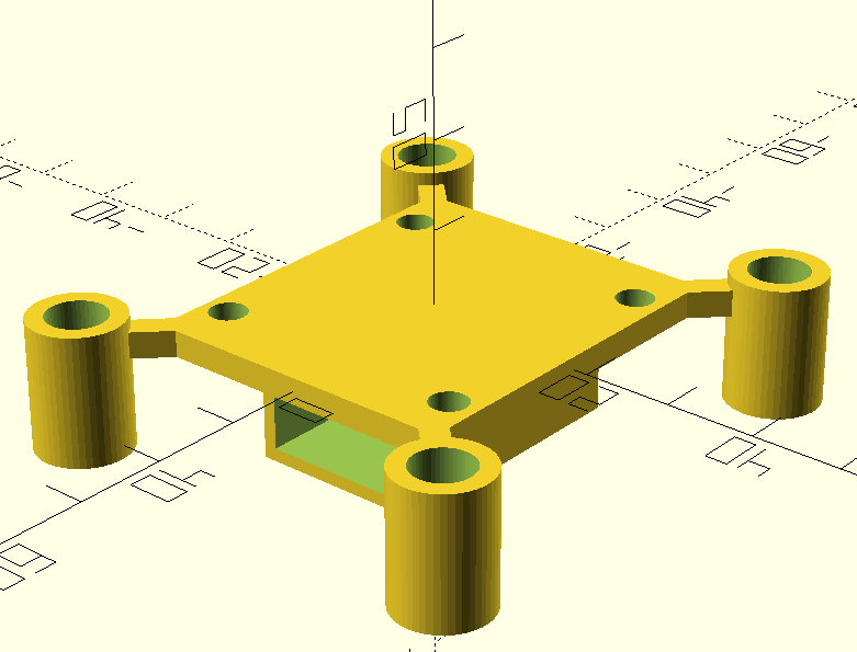
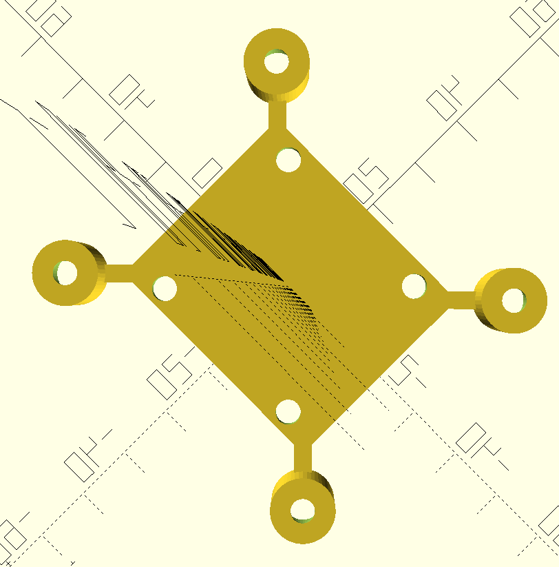
The rotors are intended to be held in by just friction. But I found hard to get the radius of the opening correct. I opted to use a bit of hot glue that the bottom of the holder to keep it in place.
Assembly
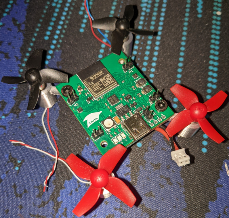
Key points:
- The frame is definitively heavier than the toy
- The screws are just a little too close the propellers (but they still spin freeing). This can be fixed fairly easily
Testing Rotors
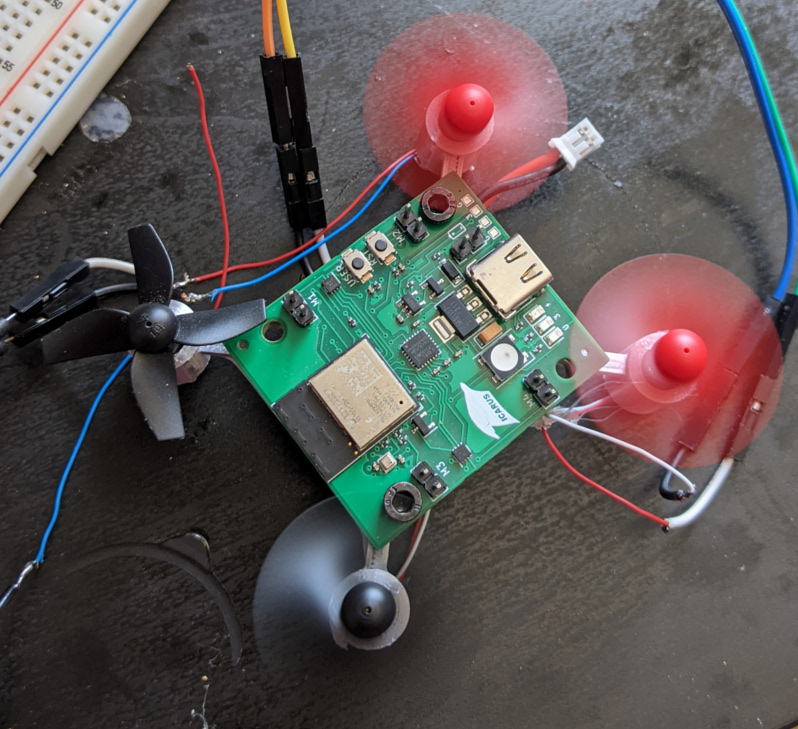
Ok so first off, at the time of the picture one of the wires to a rotor broke, so that’s why it is not spinning.
I’ve tested running the rotors right from a power supply. This was to ensure the necessary amount of current was flowing to the rotors.
What I found is that with all four rotors spinning at max speed, it wasn’t really enough to get any real lift. I did get a bit of motion, it was definitively trying its best… But it wasn’t quite enough.
So this ain’t going to work.
I figure at this point, I’ll have to commit to real drone hardware. I was reluctant about this at first, but it does have numerous advantages (standardized parts).
Future
For using real drone hardware, I’ll definitively need a PDB and a 4-in-1 ESC. But I’ll have to do more research on the parts.
1 post references this page