In my last post I showed how I was mounting sensors to my robot. The sensors include an RPLidar.
In this post I will talk about integrating the RPlidar into ROS and simulation.
Hardware
The lidar is connected to the raspberry pi using a USB serial cable. It appears in ubuntu as a generic usb uart bridge.
VID=0x10C4, PID=0xEA60 (CP210X UART Bridge)
To be able to consistently connect to the device a dev symlink is created using the following udev rule:
KERNEL=="ttyUSB*", ATTRS{idVendor}=="10c4", ATTRS{idProduct}=="ea60", MODE:="0666", SYMLINK+="rplidar"
The driver is then pointed to /dev/rplidar.
Driver
The driver is not currently available in ROS 2 Jazzy. So I build it from source
  Slamtec/rplidar_ros:
    type: git
    url: https://github.com/Slamtec/rplidar_ros.git
    version: ros2
other then that there are no issue launching and using the driver.
Simulation Setup
3D model
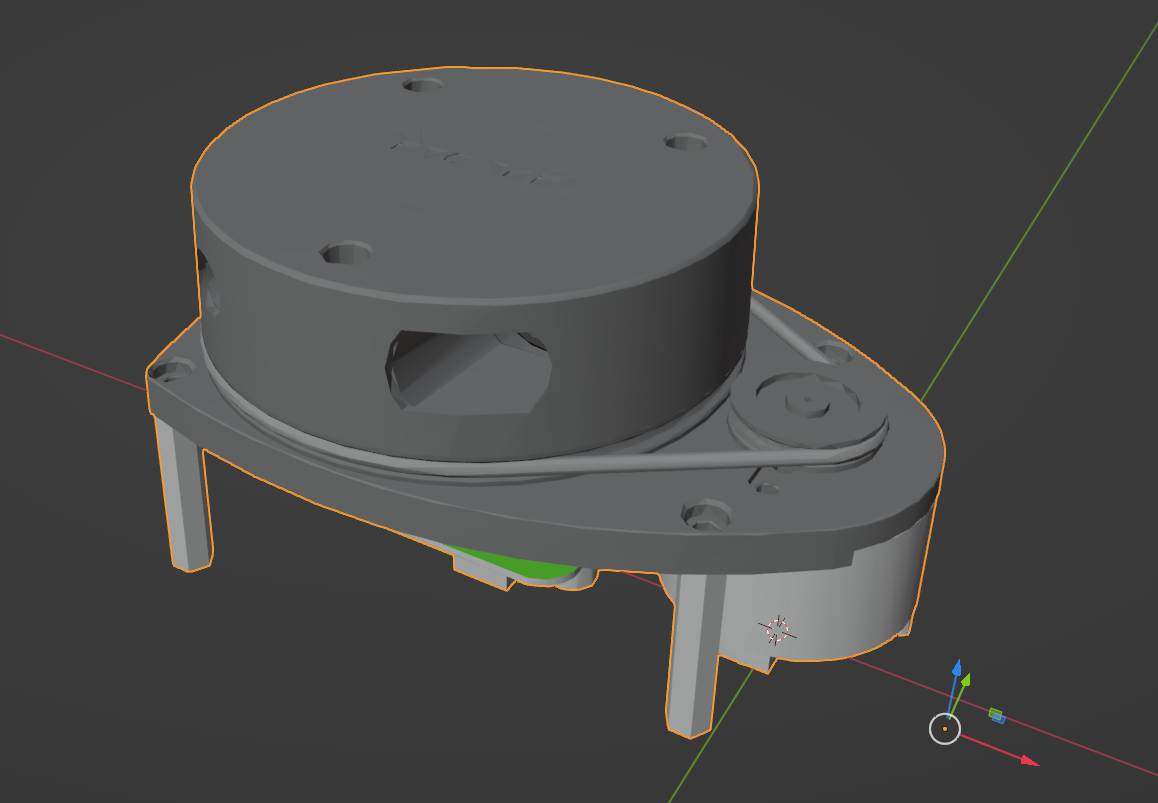
I wanted to be able to actually visualize the rplidar in the simulation. The driver package does contain the model or URDF files. But you can download the model from the manufracturer website.
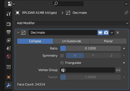
The model file from the slamtec website is high detail (even the developer kit one). So I had to reduce the polygon count.
I imported the model into blender and used the decimate modifier to reduce the polygon count.
URDF
The URDF as a couple key elements:
<robot xmlns:xacro="http://www.ros.org/wiki/xacro" name="rplidar">
  <xacro:macro name="rplidar" params="parent:=base_link xyz:='0 0 0' rpy:='0 0 0'">
  <xacro:property name="mesh_file" value="file://$(find genbu_description)/meshes/rplidar_a1m8.dae"/>
    <!-- Base of the RPLIDAR (below the center of the motor) -->
    <link name="rplidar_base_link">
      <visual>
        <geometry>
          <mesh filename="${mesh_file}" scale="1 1 1"/>
        </geometry>
      </visual>
    </link>
    <joint name="rplidar_base_joint" type="fixed">
      <parent link="${parent}"/>
      <child link="rplidar_base_link"/>
      <origin xyz="${xyz}" rpy="${rpy}"/>
    </joint>

    <!-- Laser link (position of the laser sensor ) -->
    <link name="rplidar_laser_link">
    </link>
    <joint name="rplidar_laser_joint" type="fixed">
      <parent link="rplidar_base_link"/>
      <child link="rplidar_laser_link"/>
      <origin xyz="-0.0455 0 0.042" rpy="0 0 0"/>
    </joint>

    <gazebo reference="rplidar_laser_link">
      <sensor name="lidar" type="gpu_lidar">
        <update_rate>5.5</update_rate>
        <always_on>true</always_on>
        <visualize>true</visualize>
        <topic>/scan</topic>
        <gz_frame_id>rplidar_laser_link</gz_frame_id>
    ...
- The inclusion of the mesh.
- The “base link”, the offset from the parent link
- the “laser link”, the position of the sensor from the lidars own base link
- gazebo tags for the setup of scan data in sim
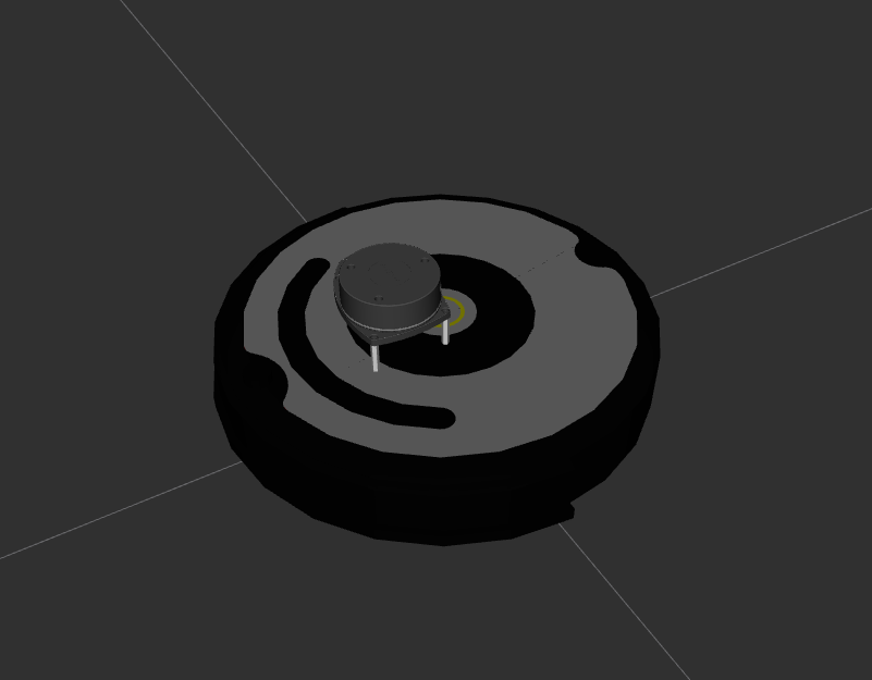
I have a base link for the rplidar so it’s easier to position on the robot itself, relative to base_link (the actual robot base link)
In rviz it looks like this
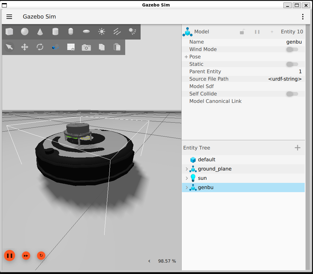
SDF setup for sim
And SDF is a “simulation description file”.
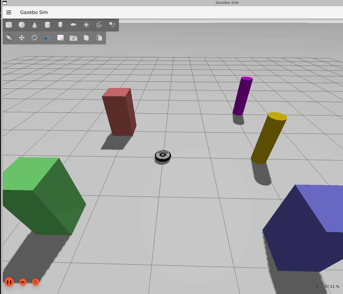
I created a SDF world file with some obstables for the robot to observe with the lidar.
In order for scan data to work it needs the following:
    <plugin
      filename="gz-sim-sensors-system"
      name="gz::sim::systems::Sensors">
      <render_engine>ogre2</render_engine>
    </plugin>
and a bridge for the gazebo topics to ROS topics
<launch>
  <!-- Bridge laser scan: Gazebo -> ROS 2 -->
  <node pkg="ros_gz_bridge" exec="parameter_bridge" name="lidar_bridge" output="screen"
      args="/scan@sensor_msgs/msg/LaserScan[gz.msgs.LaserScan" />
</launch>
The gazebo tags in the robot’s URDF are used to tell the simulation environmet to load the scan plugin.
Visualizing
Below I use a twist command to spin the robot and view the changing laser scan data.