on
Learning CAD and 3D Printing
In my quest to make cool stuff, I decided to buy myself an Ender 3 Pro 3D printer. There are all sorts of cool projects on https://www.thingiverse.com to print, but I’m personally more interested in what I can make myself.
This obviously means I need to learn some CAD software to creating crafting my own 3D models.
The programs FreeCAD and OpenSCAD, were the first tool to catch my eye. FreeCAD would be the more traditional CAD software where the user starts drawing and constraining sketches. And I found OpenSCAD interesting because it takes a coding approach with defining the geometry.
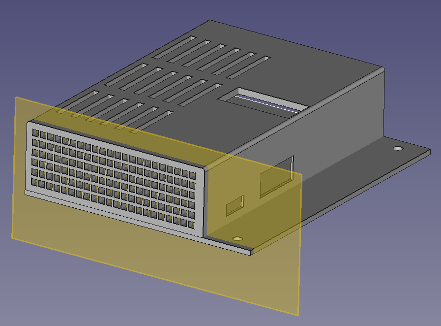
I figured I’d start small and work my way up in design complexity, so the first project I worked on was something simple and also practical: A tool holder for my Ender 3 (designed in FreeCAD).
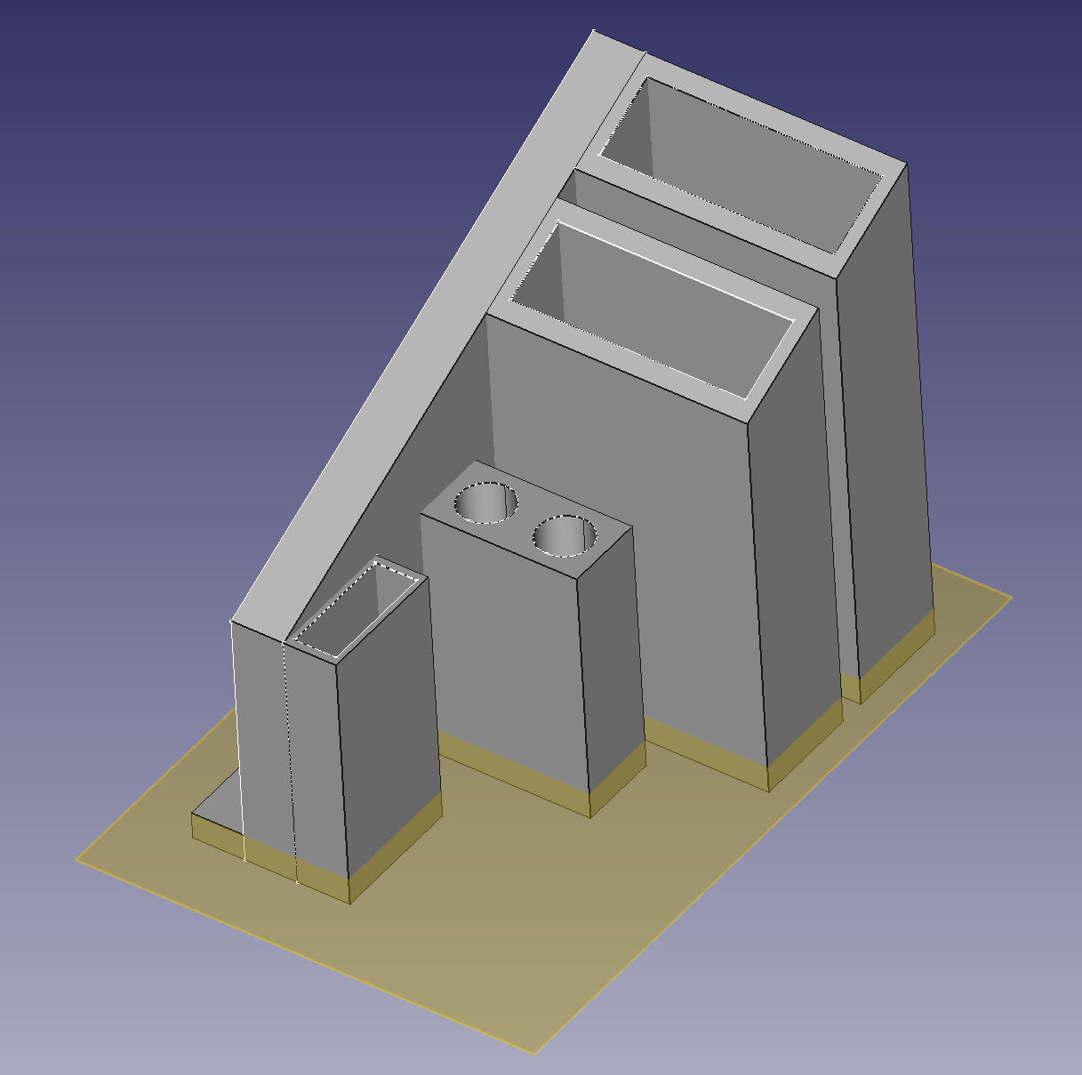
The idea is the holder nests just under the right most side of the control panel. The design is very simple. One main sketch of the base and a sketch for each individual tool holder. From the bottom up: Wrenches, hex keys and screw driver, angle cutters, spatula.
The datum plane (yellow plane) is used to create pockets for all the tools.
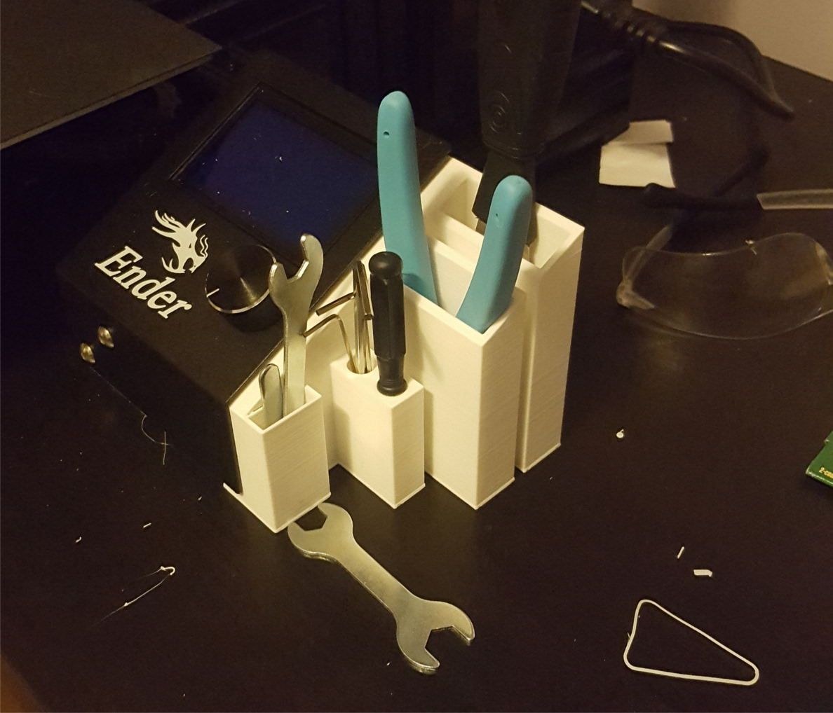
Now… I did screw up a bit here. That wrench on the table doesn’t fit.. I made the pocket the same size as the width as that wrench so there isn’t enough clearance. I’ll just keep it safe in the drawer..
Octoprint
Octoprint is a popular remote access tool for 3D printers that can run on a Raspberry Pi. As my next project in the CAD world I decided to create a bracket for connecting a Raspberry Pi 3B+ to the 3D printer.
Inspired by some other designs I’ve seen on the internet I decided to mount the Pi above the SD card slot. The main body of the bracket is just a sleeve where the Pi slides in and is held in place by friction. Though the main difference is I’ve left a space in the top for accessing the Raspberry Pi’s camera port.
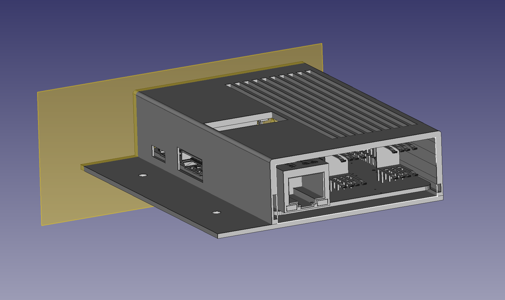
Ports for USB and HDMI are to the side and I added vents to the top and back for air flow. I played around with the idea of mounting a fan somewhere but there isn’t much clearance in this location so I decided in flavour of passive cooling (my Raspberry Pi does have a heat sink on the CPU though).
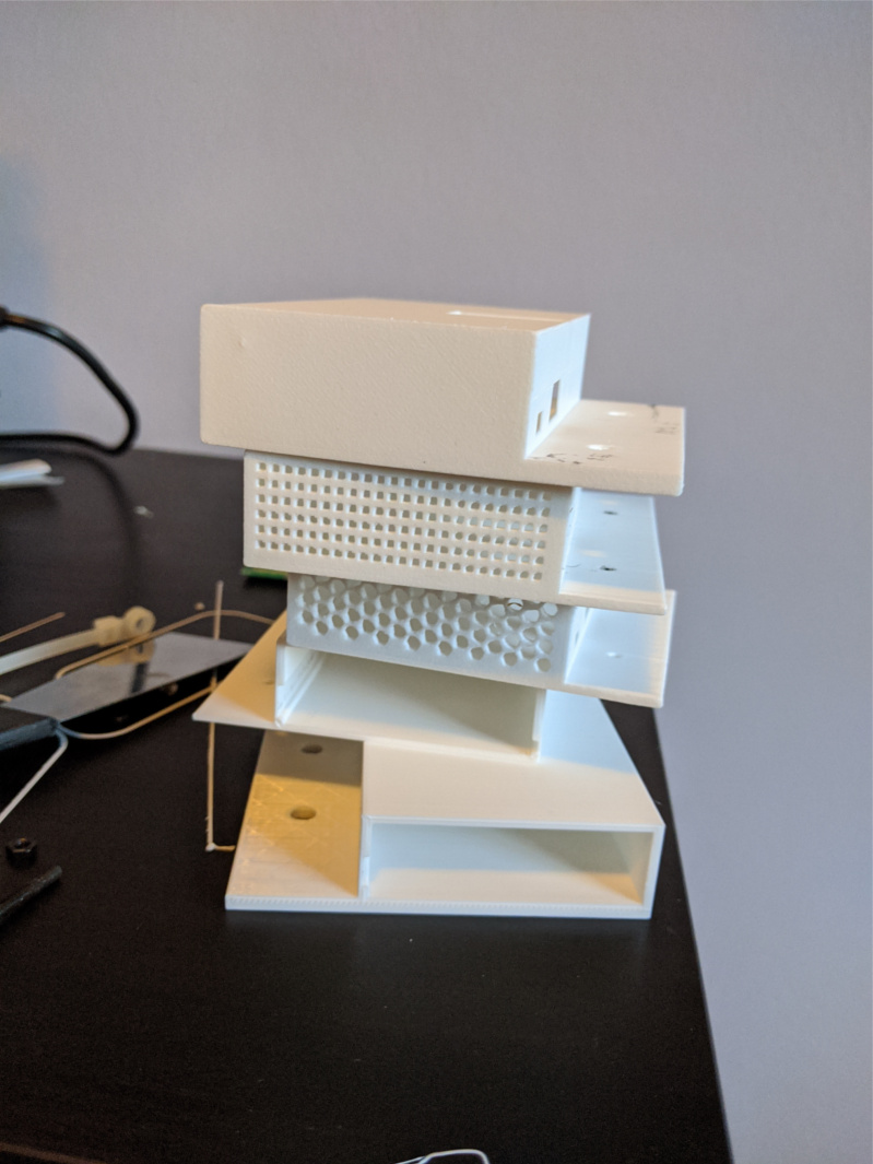
The above design I thought was pretty good however there were 3 problems:
- The hex mesh pattern on the back is cool however each hexagon is pretty small and ends up looking like a circle after printed
- The vents at the top cannot easily be printed because they are too tall and thin
- The left most screw hole slightly overlaps with the USB port, so a screw head in that position can block the USB cable
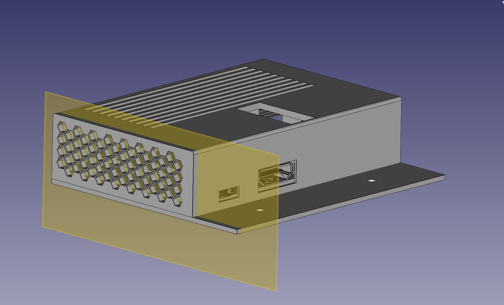
Below is an improved version.
- Square mesh pattern for back vents
- Horizontal support on the top vents for easier printing
- Screw holes are positioned closer to the edges
Measure twice, cut once
When I started with this project I took some measurements to figure out the spacing. Though while actually trying to build this model, I realize I was not careful enough with the measurements (or at least did things too quick and did not use the measurements that I had).
I iterated on this design quite a bit either because of things I missed or silly mistakes.
One silly mistake was deselecting the visibility of the camera port in FreeCAD resulting in a printed model with the camera port.
This resulted in a lot of wasted material
In the future, I’ll be using ‘vitamins’ to help understanding the size constraints and will be more careful with measurements.
Final Product
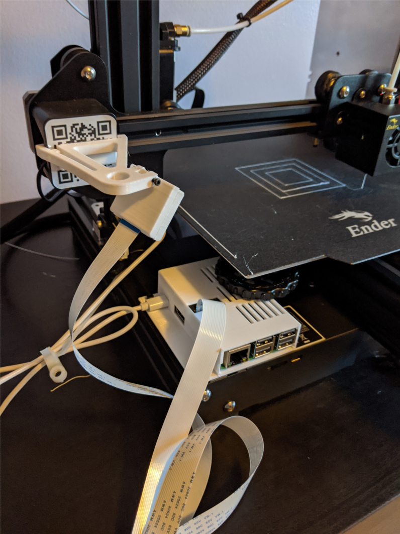
Need to clean up the excess cabling.
As an aside: The Raspberry PI is powered off the Ender 3’s power supply using a buck converted to step down the voltage.
Experience with FreeCAD
Generally speaking not fantastic. I found it to be somewhat buggy and very slow. At a certain point just making simple vertical distance constraints caused the entire UI to become unresponsive (The UI becoming unresponsive happened quite a bit). Adjusting values for linear patterns also caused the UI to lag.
On top of this, a generic CAD issue/quirk, is that if you make a large value change to a fully constrained sketch, there might be multiple solutions the solver gets to. Meaning you have to do small incremental value changed which is just not reasonable with the unresponsive UI.
For my next CAD project I’m planning on using OpenSCAD to get a feel for the coding approach to solid modelling.