on
SSD1306 OLED Display Driver using I2C
Recently I’ve been working on a new firmware library and have been writing drivers for various components. One is particular was the SSD1306 OLED display. As popular as they are, I didn’t find many references for how they work, mostly just “Use X arduino library”.
So this post will be a guide for how you can write a I2C driver for this display.
This won’t be aimed at any platform in particular, I will trying and keep the information high level so it can be ported to any device that can communicate via I2C.
I2C Summary
This is not going to be a in-depth description of I2C but here are the fundamentals:
- I2C is a master/slave protocol. Each data packet sent on the bus is 9-bits: 8-bit data, 1-bit ACK from receiver
- A device on the bus initiates a transmission by sending a
STARTcondition (making it the master, and granting it control of the bus) - The master device follows the
STARTcondition with a 7-bit slave address and 1-bit to indicate read or write mode (W = 0, R = 1) -
If write mode
4a. The master can send X bytes to the device
-
If read mode
5a. The master receives bytes from the slave device (and is required to ACK or NACK at the right time)
- The master send a
STOPcondition to end the transmission.
An I2C device could be modelled as the following (ignoring error handling):
class Device
{
public:
    Device(uint8_t address) : address{address} {}
    // Send a START condition
    void start();
    // Send a byte on the bus
    void write(uint8_t data);
    // Read a byte from the bus
    uint8_t read(bool ack);
    // Send a STOP condition
    void stop();
private:
    uint8_t address;
};
And to extend this, we can use the above to begin a transmission and end the transmission:
class Device
{
public:
    // ...

    enum class Mode
    {
        Write = 0,
        Read = 1,
    };

    // Begin I2C transmission
    void begin(Mode mode)
    {
        // Send the START condition
        start();
        // Send the Slave address + mode (referred to as SLA+RW)
        write((address << 1) | static_cast<uint8_t>(mode));
    }

    void end()
    {
        // Send a STOP condition
        stop();
    }
};
At which point we can use either write or read.
E.g.
Device oled{0x3C};
oled.begin(Device::Mode::Write);
oled.write(...);
oled.end();
SSD1306 Communication
Alright that is, roughly, how to send data over I2C now what about the display?
The following is from the SSD1306 datasheet and defines how data and command bytes are sent to the display:
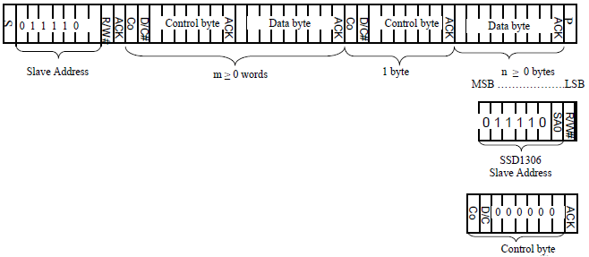
It is an I2C data frame containing:
- The start condition
S - The stop condition
P - A control byte
- N data bytes
Control Byte
Contains two relevant bits
- Co - continuation bit set to zero to indicate the following is a data byte for the command (in our case this is always zero)
- D/C - Data / command selection bit. If zero, the following byte is a command and if one, the following is GDDRAM data (data we want to put on the display)
Therefore if sending command data, the control byte is set to 0x00 and if sending GDDRAM data the control byte is set to 0x40.
Sending commands
Commands are used to configure the OLED display.
Given the above information the following has to happen to send command bytes to the display:
- Begin transmission
- Send a byte indicating command data (i.e.
0x00) - Send the byte of command data
- End transmission
class Ssd1306
{
    static constexpr uint8_t CONTROL_COMMAND = 0x00;
    static constexpr uint8_t CONTROL_DATA = 0x40;

public:
    Ssd1306(uint8_t address)
        : device{address}
    {
    }

private:
    void sendCommand(uint8_t cmd)
    {
        // Begin
        device.begin(Device::Mode::Write);
        // Send control byte
        device.write(CONTROL_COMMAND);
        // Send command byte
        device.write(cmd);
        // End
        device.end();
    }

    // I2C device
    Device device;
};
The following is an example for turning on the display:
The datasheet specifies what bytes to send

class Ssd1306
{
    // ...
    // Display on of off (normal AF vs sleep mode AE)
    static constexpr  uint8_t COMMAND_DISPLAY_ON = 0xAE;

public:
    // ...

    // Turn on the display
    void enable(bool on)
    {
        sendCommand(COMMAND_DISPLAY_ON | static_cast<uint8_t>(on));
    }

    // ...
};
Sending a multi-byte command:
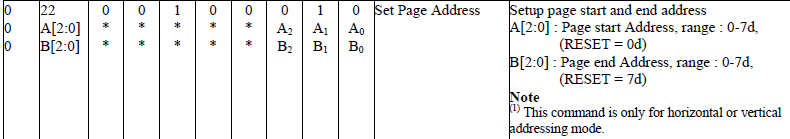
class Ssd1306
{
    // ...
    // Set page address
    static constexpr uint8_t COMMAND_SET_PAGE_ADDRESS = 0x22;

public:
    // ...

    // Set the start and end page addresses
    void setPageAddress(uint8_t start, uint8_t end)
    {
        sendCommand(COMMAND_SET_PAGE_ADDRESS);
        sendCommand(start & 0x07);
        sendCommand(end & 0x07);
    }

    // ...
};
Display initialization
It is necessary to do the start up sequence to initialize the display (this is contained in the datasheet).
Startup sequence:
- Set MUX Ratio [$A8, $3F]
- Set display offset [$D3, $00]
- Set start line [$40]
- Set segment re-map $A0 / $A1
- Set COM output scan direction $C0 / $C8
- Set COM pin hardware configuration [$DA, $02]
- Set contrast [$81, $7F]
- Resume the display $A4
- Set Oscillator frequency [$D5, $80]
- Enable charge pump [$8D, $14]
- Turn the display on $AF
In particular due make sure the charge pump config is set correctly or the display will not be powered.
Sending GDDRAM data
Sending graphics data is similar, but in this case we want to allow sending a byte buffer that contains the display data:
class Ssd1306
{
    // ...
public:
    // Send a data buffer GDDRAM
    void sendBuffer(const uint8_t* buffer, unsigned long length)
    {
        device.begin(Device::Mode::Write)
        device.write(CONTROL_DATA);
        for (auto i = 0u; i < length; ++i)
        {
            device.write(buffer[i]);
        }
        device.end();
    }

    // ...
};
Display RAM
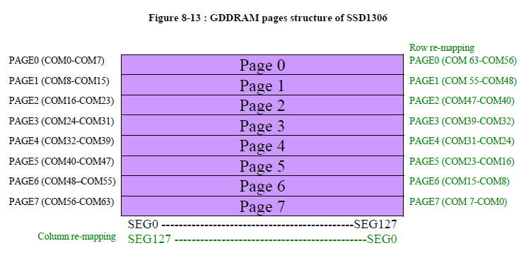
The display memory is separate into 8 pages, each containing 8 rows (COM) and 128 columns (SEG).
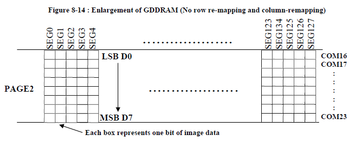
Each byte of data you send to the display will populate all 8 rows of the page at the current column. With the LSB populating the upper most row.
Addressing Modes
The display has three different addressing modes: Page, Horizontal and Vertical. This will control where the cursor moves after writing a byte to the display RAM.
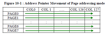
Cursor stays in the current page.
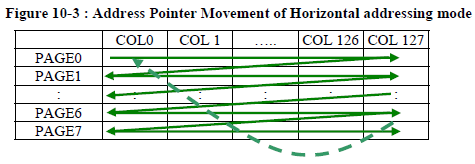
Cursor will move horizontally along the page and move down to the next page after writing to the last column.
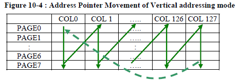
Cursor will move down the pages then back up to the start of the next column.
Drawing
Before drawing to the display we have to be able to control where the data is being drawn. This is done by setting the column start and end address, as well as the page start and end addresses.
Once the end address is reached (for the page or the column), the address is moved back to the start.
class Ssd1306
{
    // ...
    // Set column address
    static constexpr uint8_t COMMAND_COLUMN_ADDRESS = 0x21;
    // Set page address
    static constexpr uint8_t COMMAND_SET_PAGE_ADDRESS = 0x22;

    // Set start and end column addresses (COL0 - COL127)
    void setColumnAddress(uint8_t start, uint8_t end)
    {
        sendCommand(COMMAND_COLUMN_ADDRESS);
        sendCommand(start);
        sendCommand(end);
    }

    // ...

    // Set the start and end pages (PAGE0-PAGE7)
    void setPageAddress(uint8_t start, uint8_t end)
    {
        sendCommand(COMMAND_SET_PAGE_ADDRESS);
        sendCommand(start & 0x07);
        sendCommand(end & 0x07);
    }
};
The easiest way to test drawing into display RAM would probably be to fill the first page with 1s.
// Create the driver. 0x3C is the default address
Ssd1306 oled{0x3C};
oled.initialize();

// Display RAM page buffer
// 128 columns (each bit in each byte is a row pixel)
uint8_t page_buffer[128];
// Fix the page buffer with 1s (all pixels on)
memset(page_buffer, 0xFF, sizeof(page_buffer));

// Set the column bounds to the full width of the display
// This also set the current column to 0
oled.setColumnAddress(0, 127);
// Set the page bounds to all pages
oled.setPageAddress(0, 7);

// Send the buffer to the display
oled.sendBuffer(page_buffer, sizeof(page_buffer));
Framebuffers
When doing more elaborate drawing operations it makes sense to first draw into a frame buffer and then update the display in one go.
class Display
{
    static constexpr uint8_t NUM_COLUMNS = 128;
    static constexpr uint8_t NUM_PAGES = 8;
    static constexpr uint8_t NUM_ROWS_PER_PAGE = 8;

public:
    Display(uint8_t address)
        : oled{address}
    {
    }

private:
    // Array of bytes for a single page
    using PageBuffer = uint8_t[NUM_COLUMNS];
    // Array of pages to model the entire display
    using FrameBuffer = PageBuffer[NUM_PAGES];

    FrameBuffer framebuffer;

    Ssd1306 oled;

};
Now the way this framebuffer is setup requires Horizontal addressing mode, so we have to keep that in mind when drawing.
class Ssd1306
{
    // Addressing mode
    static constexpr uint8_t COMMAND_ADDRESSING_MODE = 0x20;

    // ...

    void setAddressingMode(uint8_t mode)
    {
        sendCommand(COMMAND_ADDRESSING_MODE);
        sendCommand(static_cast<uint8_t>(mode));
    }
};
To draw into the framebuffer we have to calculate the page and row number.
class Display
{
public:
    // ...

    // Set a pixel in the display
    void drawPixel(unsigned int col unsigned int row, uint8_t pixel)
    {
        // Get the page the row exists at
        auto& page = framebuffer[row / NUM_ROWS_PER_PAGE];
        // Get the page within the page (0-7)
        const auto page_row = row % NUM_ROWS_PER_PAGE;
        // Set the corresponding bit to set the pixel
        page[col] = (page[col] & ~(1 << page_row)) | (pixel << page_row);
    }
};
To update the display, send the entire buffer. Also ensure horizontal addressing mode is set.
class Display
{
public:
    // ...
    void initialize()
    {
        oled.initialize();
        oled.setAddressingMode(0x00);
    }

    void update()
    {
        oled.setColumnAddress(0, 127);
        oled.setPageAddress(0, 7);
        oled.sendBuffer(&framebuffer_[0][0], sizeof(framebuffer_));
    }
};
Display display{0x3C};
display.initialize();

display.drawPixel(0, 0, 1);
display.drawPixel(1, 0, 1);
display.drawPixel(2, 0, 1);
display.drawPixel(3, 0, 1);
display.drawPixel(4, 0, 1);

display.update();
In a future post I’m going to highlight a project I’m working on that will involve hardware abstraction and wil reference back to the I2C portion of this article.
1 post references this page