Not a lot of progress this month but I did get the drone assembled and electronics wired up.

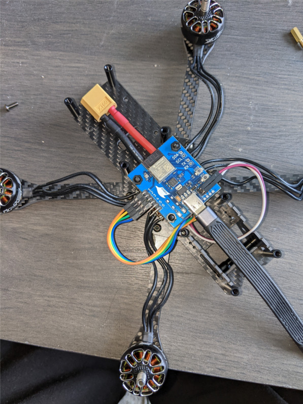
The Icarus FC is mounted above a 4-in-1 ESC that controls the rotors.
A few glaring issues:
- The wires are intentionally too long. I did that to give myself some room to re-wire as needed
- The USB connector is on the front of the drone so I need this awkward USB-C extension to be able to re-program without taking the top plate off
A few zip ties keeps things sane.
I exercised each motor and confirmed they were working. I also confirmed the motor directions were correct (had to do some re-wiring).

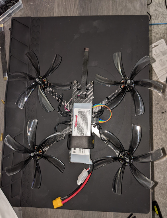
Full assembled.
I did an initial thrust test to confirm the props could generate enough force to create lift… Let’s just say… it should be fine. These motors an crazy powerful.
Completely unrelated to the above… But I learned I should wire in some sort of quick disconnect on the FC. I was thinking of a jumper that connects the MCU RST line to a pull-down and a use another jump to pull-up to VCC. Then yank the jumper if things go south.
Now while I knew this would be hard to test in general, actually being at this point now it really hit me just how much. In order to test the PID code I’m thinking of 3D printing a base that I can zip tie the drone to and the base can tilt on a rod.
This drone is pretty chunky as well. My original plan was to do micro-quad size but I designed the FC around 30mmx30mm mounting pattern and I found that the’re are not many microquad frames with 30x30 mounting holes.
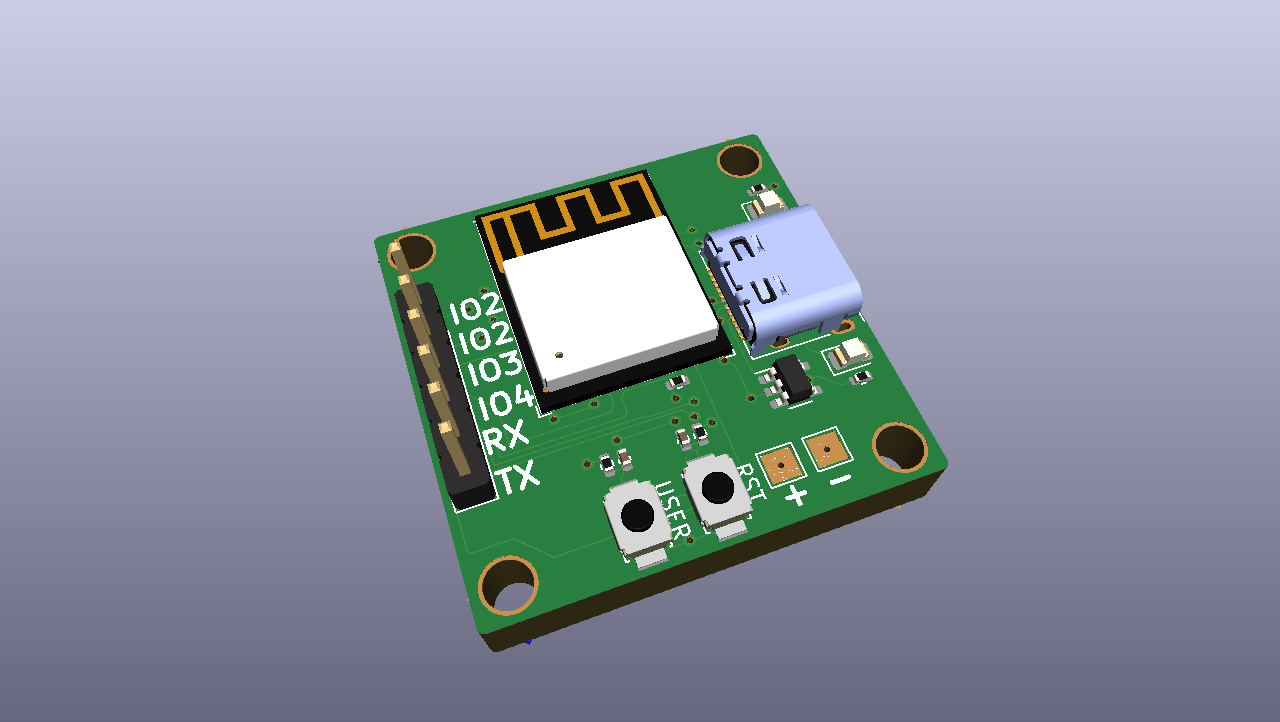
So I think I’ll attempt to down size a bit and this might involve multiple FC stacks. I’ve started on an ESP32-C3 BLE stack already:

This is basically the ESP32-C3 Devboard in a 25mmx25mm mounting pattern.
An Icarus re-design will probably be next. But I’ll see how far I get with the current rev first.
1 post references this page