on
STM32F4 Devboard
In my last post I mentioned wanting to split the Bluetooth receiver into a separate stack. The main reason for this being that the ESP32-C3 does not have enough outputs to support 4 DSHOT channels.
I haven’t settled on what approach to take (so no re-design of Icarus planned yet), but I figured I’d need to test out a few new MCUs either way.
My top candidates at the moment would be STM32F3/F4 or the RP2040.
I started with the F4 as these are pretty typical in the FC world.
Design
Not much different from the usual devboard schematic but I’ll go over it quickly.
I’ve selected an STM32F405RGT6
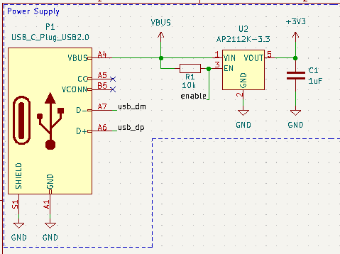
Power supply
USB-C connector with VBUS connected to a 3.3V regulator.
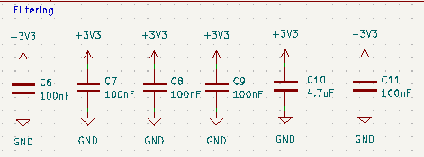
Necessary filtering for the MCU.
MCU
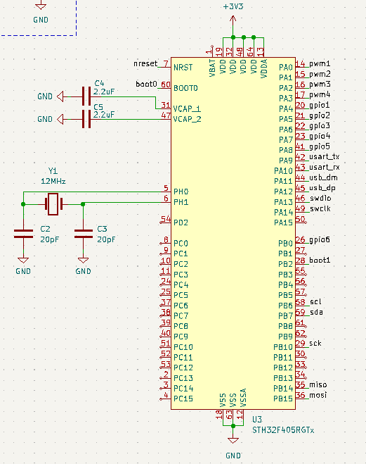
I was a bit worried about the oscillator design. It can get a bit complicated if you read into it. I found a crystal with what looked like common drive level values and selected the caps the part was intended to work with (so basically winged it).
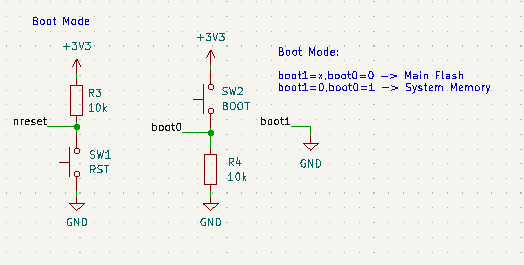
MCU boot configuration:
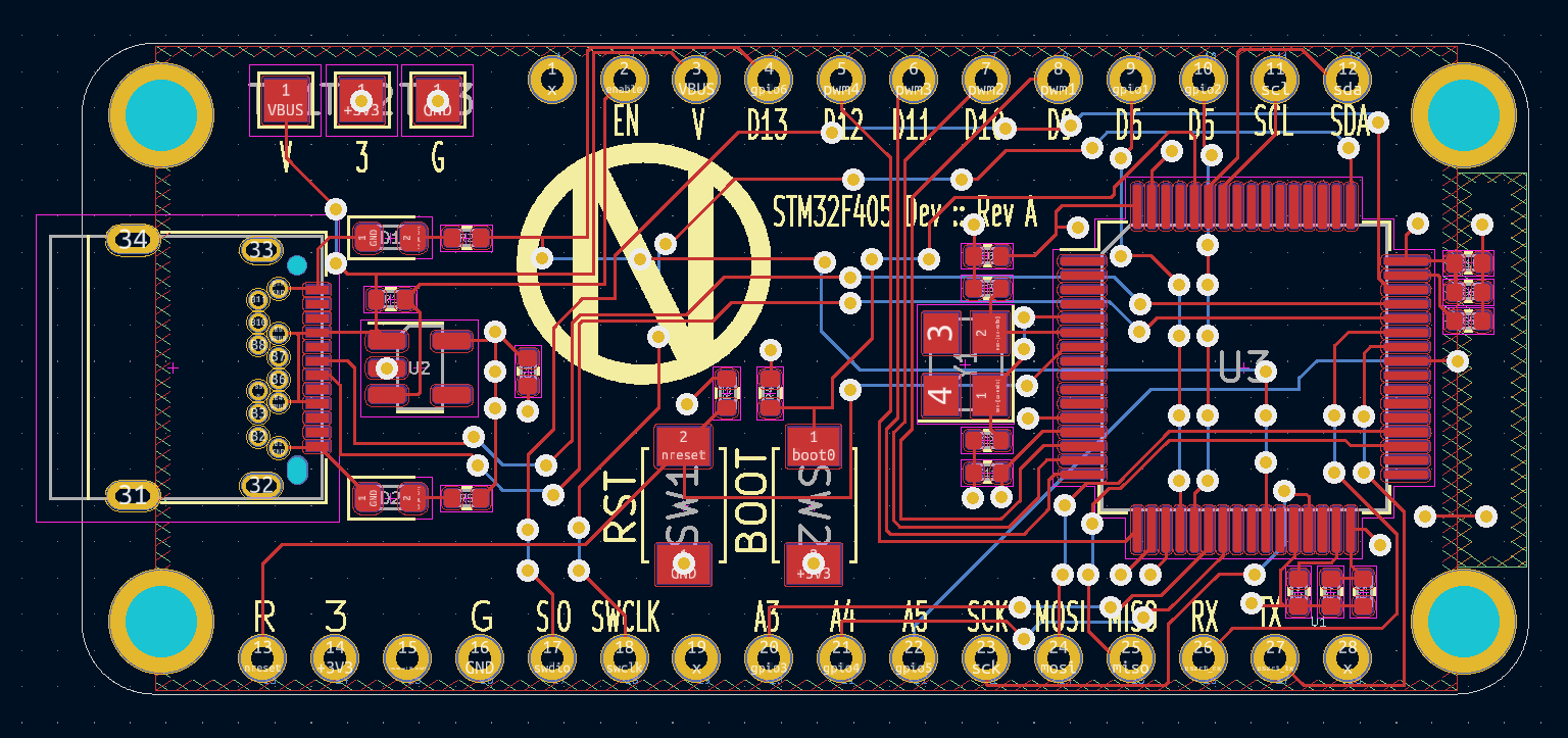
PCB Layout
Again going with the Adafruit Feather layout.
More of a tangent but got KiBot to generate some nice looking 3D models:
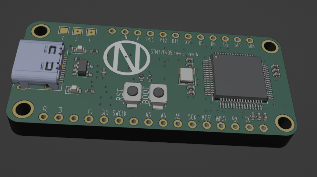
Note: All fabrication files and 3D models are generated and can be found here
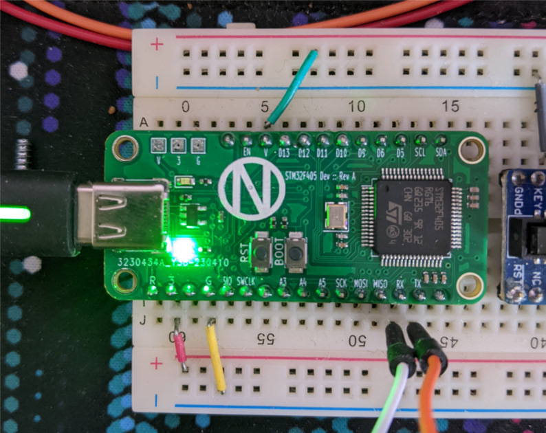
Assembled Board
Bring up
The mistake I make with Icarus Rev A was I used a resonator package in the HSE BYPASS mode (direct clock input). The built-in bootloader doesn’t work with this option, so DFU flashing was not possible.
This time around I’m using a typical external crystal oscillator.
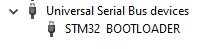
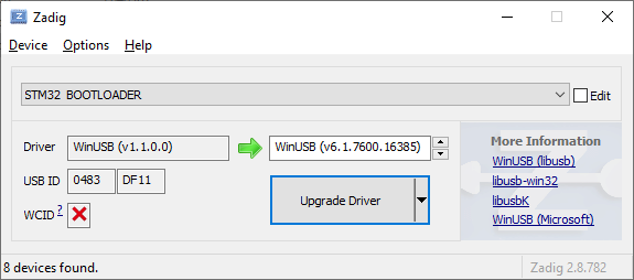
The first true test is to see if I can put the board in bootloader mode and my computer recognizes it.
Which it did!
The WinUSB driver needs to be installed before it’s usable. I did this with Zadig.
Programming (C++)
Using STM32Cube IDE I setup a simple blink + serial write program. This is the first time I used this software. The HAL setup is quite seamless.
/* Private user code ---------------------------------------------------------*/
/* USER CODE BEGIN 0 */
static const uint8_t TEST[] = "Hello World\r\n";

// ...

int main(void)
{
    // ...

    /* Infinite loop */
    /* USER CODE BEGIN WHILE */
    while (1)
    {
        /* USER CODE END WHILE */

        /* USER CODE BEGIN 3 */
        HAL_UART_Transmit(&huart1, TEST, sizeof(TEST), 10);
        HAL_GPIO_TogglePin(GPIOB, GPIO_PIN_0);
        HAL_Delay(1000);
    }

  // ...
}

// ...
I don’t have an ST-LINK so I put the board into bootloader mode and flashed it with the STM32 Programmer tool.
And had a successful hello-world program!
Programming (Rust)
Of course.. Now Rust.
Had to copy the linker file over from the STM32 IDE.
/* memory.x */

/* Memories definition */
MEMORY
{
  CCMRAM (xrw) : ORIGIN = 0x10000000, LENGTH = 64K
  RAM    (xrw) : ORIGIN = 0x20000000, LENGTH = 128K
  FLASH  (rx)  : ORIGIN = 0x8000000,  LENGTH = 1024K
}

/* Sections */
SECTIONS
{
  /* The startup code into "FLASH" Rom type memory */
  .isr_vector :
  {
    . = ALIGN(4);
    KEEP(*(.isr_vector)) /* Startup code */
    . = ALIGN(4);
  } >FLASH
}
#![no_std]
#![no_main]

use panic_halt as _;

use stm32f4xx_hal::{
    pac,
    prelude::*
};
use core::fmt::Write;

#[cortex_m_rt::entry]
fn main() -> ! {
    let dp = pac::Peripherals::take().unwrap();

    let rcc = dp.RCC.constrain();
    let clocks = rcc.cfgr.use_hse(12.MHz()).freeze();

    let mut delay = dp.TIM1.delay_ms(&clocks);

    let gpioa = dp.GPIOA.split();
    let gpiob = dp.GPIOB.split();

    let tx_pin = gpioa.pa9.into_alternate();
    let mut tx = dp.USART1.tx(tx_pin, 115200.bps(), &clocks).unwrap();

    let mut led = gpiob.pb0.into_push_pull_output();
    led.set_high();

    loop {
        writeln!(tx, "Hello World\r\n").unwrap();
        led.toggle();
        delay.delay(1.secs());
    }
}
The equivalent code is much more simple in Rust…
Future work
Connecting this board to my ESP32-C3 board over some serial interface.
1 post references this page